Centrifugal blower for relieving stress concentration for vane plate coupling part
A stress concentration, blower technology, applied in mechanical equipment, machines/engines, liquid fuel engines, etc., can solve the problems of increased inertial weight of the vane wheel, increased starting time, increased weight of the vane wheel or increased material costs, etc., to save energy. Effect
Active Publication Date: 2008-11-19
株式会社泰拉尔极东
View PDF2 Cites 0 Cited by
- Summary
- Abstract
- Description
- Claims
- Application Information
AI Technical Summary
Problems solved by technology
However, in this case, there will be an increase in the weight or material cost of the blade wheel
Moreover, the increase in the weight of the blade wheel will cause the increase of the inertial weight of the blade wheel, which increases the starting time of the blower when it is running, and the problem that it cannot be started by using the general-purpose motor torque, or in the general-purpose motor overload protection device. , resulting in the problem of poor starting caused by wrong action
In addition, since a special motor or a motor overload protection device is used to enable the blower to start, there is a problem that it becomes uneconomical in saving resources and energy.
Method used
View moreImage
Smart ImageViewing Examples
Examples
Embodiment Construction
Login to View More PUM
 Abstract
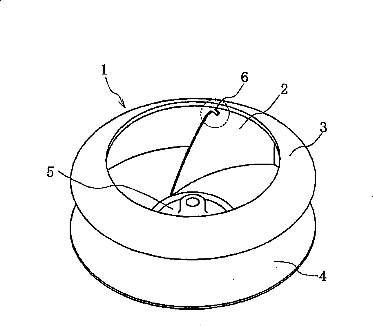
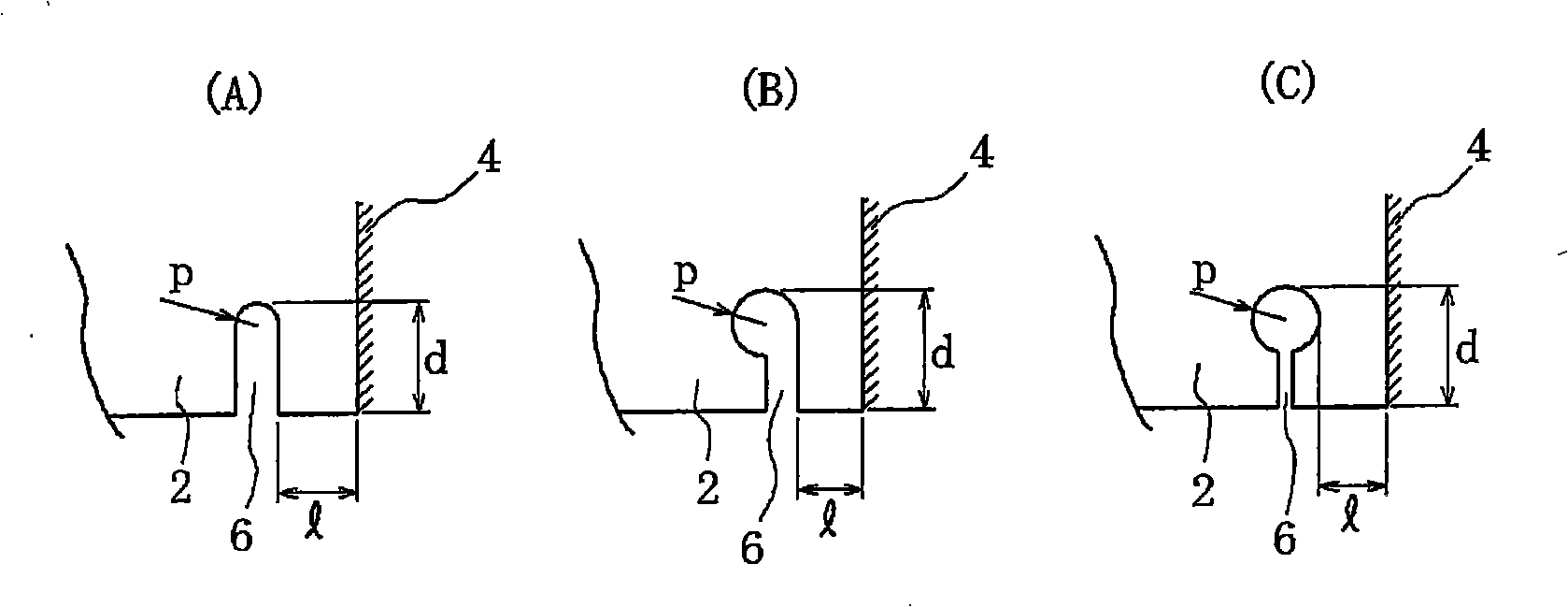
The invention aims to provide a centrifugal blower with a backward blade wheel, which alleviates the stress concentration born by a joint part of a blade board. The centrifugal blower has a preshaped cut part with a preset shape on the edge of the blade board and close to the joint part with a shield, so as to alleviate the stress concentration of the joint part of the blade board. The shape of the gap is formed by walls parallel to each other and a curved bottom which connects the two walls.
Description
Centrifugal blower that reduces stress concentration on blade joints technical field The present invention relates to a centrifugal blower with backward blade wheels used as ventilation equipment for various air supply and exhaust, painting equipment, dust collecting devices, factories, etc. Background technique The backward blade wheel of the centrifugal blower has the outlet of the blade plate facing the radial direction, and the outlet angle of the blade plate is facing the rear (30°~60°), and the blade plate that is curved from the inlet to the outlet is in the The main board and side boards of equal thickness are fixed by welding or riveting. In addition, the main plate is fixed by welding or riveting to the shaft portion formed to shape the flow path of the impeller inlet. Furthermore, at the inlet of the blade wheel, an annular portion called a shroud is connected to the outer edge portion of the blade plate by welding or the like, so that air introduction to the b...
Claims
Login to View More Application Information
Patent Timeline
 IPC IPC(8): F04D29/30
Inventor 永井秀满藤井繁满
Owner 株式会社泰拉尔极东
Features
- R&D
- Intellectual Property
- Life Sciences
- Materials
- Tech Scout
- Unparalleled Data Quality
- Higher Quality Content
- 60% Fewer Hallucinations
Learn More Browse by: Latest US Patents, China's latest patents, Technical Efficacy Thesaurus, Application Domain, Technology Topic, Popular Technical Reports.
© 2025 PatSnap. All rights reserved.Legal|Privacy policy|Modern Slavery Act Transparency Statement|Sitemap|About US| Contact US: help@patsnap.com


