Split type chain sprocket splicing structure

A split-type, sprocket technology, used in belts/chains/gears, portable lifting devices, components with teeth, etc., can solve the problems of weakened chain shaft strength, cumbersome installation, short service life, etc., to achieve stable performance, Easy installation and disassembly, long service life

Inactive Publication Date: 2008-11-19
SUZHOU JIANGNANLV ELECTROMECHANICAL TECH GROUP +1
View PDF0 Cites 11 Cited by
  • Summary
  • Abstract
  • Description
  • Claims
  • Application Information

AI Technical Summary

Problems solved by technology

In the existing split sprocket structure, in order to ensure that there is no relative rotation between the half-wheel connection and the chain shaft, the two half-sprockets must be fixed to the chain shaft. Punching pin holes on the chain shaft is cumbersome to operate on site; during the rotation of the sprocket, the bolts and pins will be affected by centrifugal force, which is prone to failure; in addition, if double-row sprockets are used, the Therefore, the diameter of the bolts and pins used will be reduced accordingly, and the bolts and pins are difficult to withstand the large shear force generated when the sprocket is running, and the bolts and pins are easy to break; after drilling a lot of holes on the chain shaft , the strength of the chain shaft will also be weakened
[0003] Due to the above reasons, the existing split sprocket structure is usually cumbersome to install, prone to failure and short in service life

Method used


Image

  • Split type chain sprocket splicing structure
  • Split type chain sprocket splicing structure

Examples


Embodiment

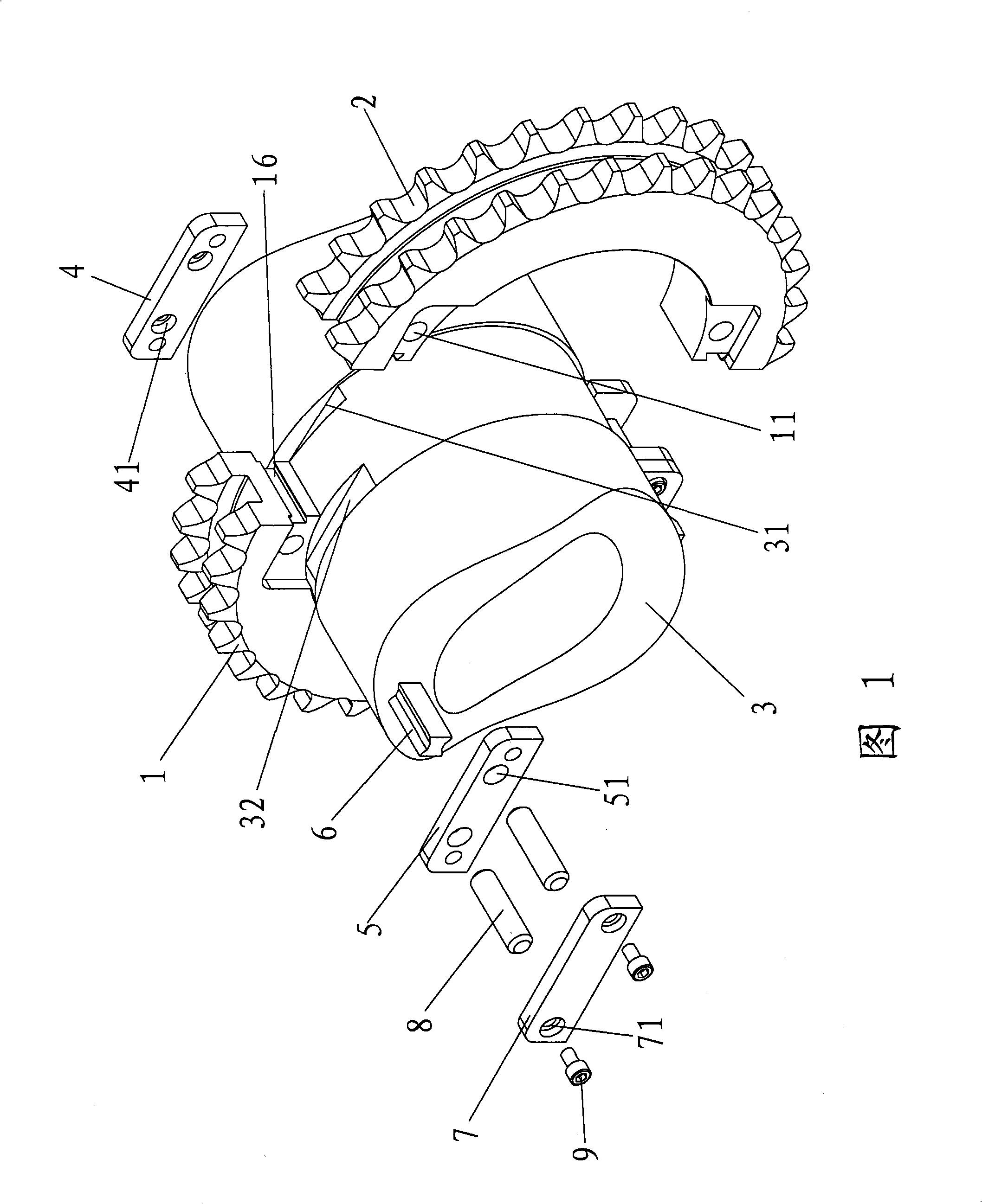
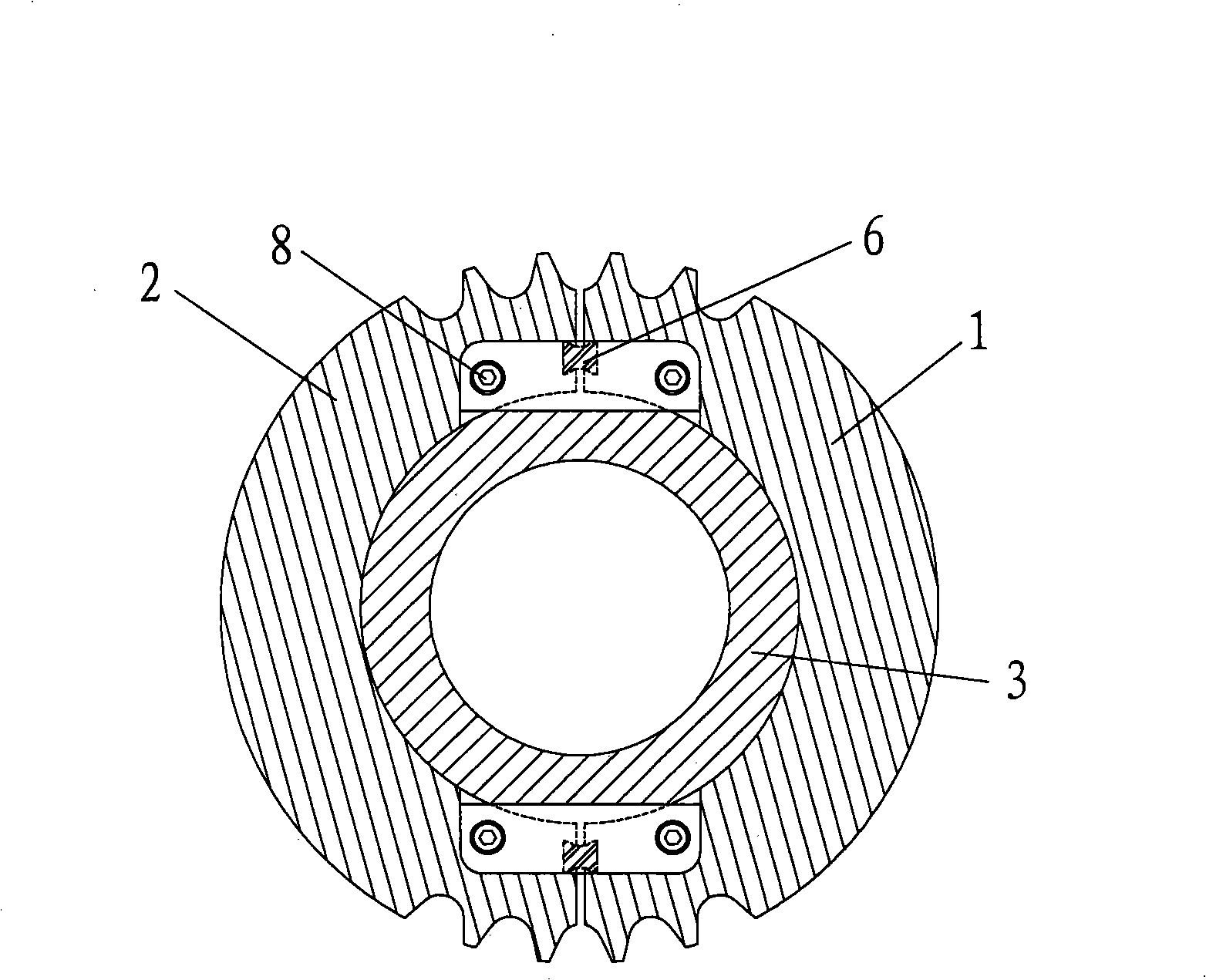
[0020] Referring to Fig. 1, a splicing splicing structure of a split type sprocket includes a sprocket and a sprocket 3 used in conjunction with the sprocket. The sprocket includes two spliced ​​half-wheels 1 and 2, wherein half-wheel 1 The fastening connection structures for fixedly connecting the sprocket wheel and the chain shaft 3 are respectively provided at the two splicing places between the half wheel 2 and the half wheel 2. As shown in Figure 1, there is a fastening connection structure at the upper and lower joints.

[0021] The fastening connection structure includes: a first groove 31 and a second groove 32 are respectively provided on both sides of the chain shaft 3 where the two half-wheels are spliced ​​along the circumferential direction, and the first groove 31 is clamped in the first groove 31. A pressing plate 4, a second pressing plate 5 clamped in the second groove 32, the first pressing plate 4, the two half-wheels 1 or 2 and the second pressing plate 5 a...


PUM


Abstract

The invention discloses a split type sprocket splicing structure, comprising a sprocket formed by matching and splicing two half wheels, as well as a chain shaft. Two splicing parts between the two half wheels are respectively provided with a fastening-connecting structure which fixes the sprocket with the chain shaft. The fastening-connecting structure is completely different from a fixation method of bolts and pins in the prior art, wherein two sides of the two half wheel splicing parts on the chain shaft are respectively provided with a first groove and a second groove along the circumferential direction; a first compression plate clamped in the first groove and a second compression plate clamped in the second groove are fixed with the two half wheels through a fastener. Therefore, the first compression plate and the second compression plate, together with groove planes on the chain shaft, can jointly play a role in bonding, prevent the relative rotation between the sprocket and the chain shaft and bear sufficient shearing force. The structure does not need on-site matching process, is simpler and more convenient to install, detach and operate, stabler in performance and longer in life-span.

Description

technical field [0001] The invention relates to a sprocket structure, in particular to a splicing structure of split sprockets. Background technique [0002] The sprocket structure is widely used in the mechanical field, such as chain drive escalators, chain drive motor vehicles, etc. In the existing split sprocket structure, in order to ensure that there is no relative rotation between the half-wheel connection and the chain shaft, the two half-sprockets must be fixed to the chain shaft. Punching pin holes on the chain shaft is cumbersome to operate on site; during the rotation of the sprocket, the bolts and pins will be affected by centrifugal force, which is prone to failure; in addition, if double-row sprockets are used, the Therefore, the diameter of the bolts and pins used will be reduced accordingly, and the bolts and pins are difficult to withstand the large shear force generated when the sprocket is running, and the bolts and pins are easy to break; after drilling ...

Claims


Application Information

Patent Timeline
Patent Type & Authority Applications(China)
IPC IPC(8): F16H55/30F16B1/00
Inventor 沈秋荪马菁华
Owner SUZHOU JIANGNANLV ELECTROMECHANICAL TECH GROUP
Why Eureka
Try Eureka