
New energy vehicle fuel cell storage device

A technology of new energy vehicles and fuel cells, which is applied in the direction of secondary batteries, battery pack components, and isolation of batteries from their environment. Avoid wear and other problems, achieve the effect of easy installation and disassembly, reduce frictional resistance, and avoid pollution

Inactive Publication Date: 2018-11-06
利辛县祥腾信息科技有限公司
View PDF0 Cites 3 Cited by
  • Summary
  • Abstract
  • Description
  • Claims
  • Application Information

AI Technical Summary

Problems solved by technology

[0003] However, the existing fuel cell storage device for new energy vehicles has some shortcomings during use. It is not flexible and convenient during the installation and disassembly of the battery pack, and will be affected by large frictional resistance. At the same time, the connection of the storage shell The wear phenomenon is more serious, which reduces the practicality of the storage device

Method used


Image

  • New energy vehicle fuel cell storage device
  • New energy vehicle fuel cell storage device
  • New energy vehicle fuel cell storage device

Examples


Embodiment 1

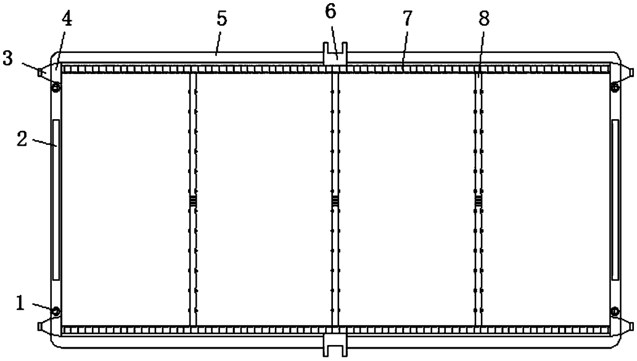
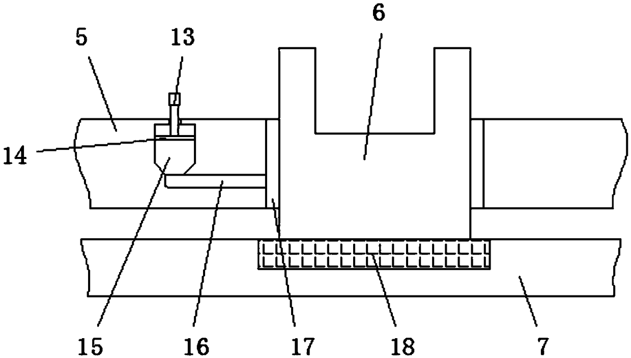
[0027] Embodiment one, with reference to figure 1 , image 3 and Figure 4 , a new energy vehicle fuel cell storage device, including a housing 5, a limiting groove 2 is opened at the center of the vertical end surfaces on both sides of the housing 5, and the vertical end surfaces on both sides of the housing 5 are located in the limiting groove 2 There are positioning grooves 1 on both sides symmetrically, the top of the housing 5 is clamped and fixed with the cover plate 20 through the positioning groove 1, the bottom of the housing 5 is clamped and fixed with the bottom plate 21 through the positioning groove 1, and the two sides of the housing 5 are horizontal A transmission rod 6 is threaded inside the end, and a pressure plate 7 is movably connected to the inner side of the transmission rod 6 , and a bearing 18 is arranged at the inner center of the pressure plate 7 and on the surface of the transmission rod 6 .

Embodiment 2

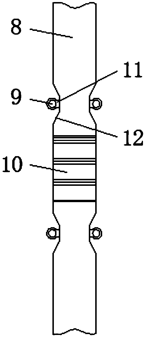
[0028] Embodiment two, refer to Figure 1-2 , the two pressure bearing plates 7 are connected by a partition plate 8, grooves 12 are symmetrically opened on both sides of the outer wall of the partition plate 8, and the inner surface wall of the vertical end of the groove 12 is welded with a connecting rod 11, connected The outer side of the rod 11 is rotatably connected with rollers 9, and the partition plate 8 with a parallel and equidistant structure can effectively separate the battery packs inside the casing 5, ensuring that the mutual independence between the battery packs is not affected, and at the same time, when the battery packs When the battery pack is embedded between the partition plates 8 to move, the rollers 9 will play a role of rolling friction on the outer walls of both sides of the battery pack, reducing the impact of frictional resistance when the battery pack moves, thereby facilitating the installation and disassembly of the battery pack .

Embodiment 3

[0029] Embodiment three, refer to figure 1 and Figure 4 , the opening end of the inner surface wall of the positioning groove 1 is provided with an elastic mesh cover 19, and the center of the surface of the elastic mesh cover 19 is provided with a round hole, the inner surfaces of the top plate 21 and the cover plate 20 and the positions corresponding to the positioning groove 1 are all The positioning post is welded, so that the cover plate 20 and the bottom plate 21 can fix the storage device as a whole through the mutual clamping of the positioning post and the positioning slot 1, and when the positioning post is embedded in the positioning slot 1, the positioning post will pass through the elastic net The circular hole on the surface of the cover 19, and extrudes the elastic mesh cover 19, so that the inner diameter of the circular hole on the surface of the elastic mesh cover 19 becomes larger, and then plays a role of sealing protection for the connection between the p...


PUM


Abstract

A new energy vehicle fuel cell storage device includes a housing, the horizontal ends of both sides of the shell are internally threadably connected with transmission rods, and the inner side of the transmission rod is movably connected with a pressure bearing plate, an oil storage bin is arranged inside the housing and on one side of the transmission rod, the inner surface wall of the oil storagebin is provided with a pushing plate and a rotating rod matched with the pushing plate, the bottom of the oil storage bin is connected with one end of the oil guide pipe, and the other side of the oil guide pipe is connected with the oil permeating plate of the outer wall of the transmission rod, the two pressure bearing plates are connected through a partition plate, the outer walls of the two sides of the partition plate are symmetrically provided with grooves, the inner surface wall of the vertical end of the groove is welded with a connecting rod, and the outer side of the connecting rodis rotatably connected with a roller. In the invention, the whole structure design of the battery storage device is simple and reasonable, the installation and disassembly operation of the battery pack are convenient, the heat dissipation performance is improved, and the battery storage device has strong practicability.

Description

technical field [0001] The invention relates to the technical field of new energy vehicles, in particular to a fuel cell storage device for new energy vehicles. Background technique [0002] New energy vehicles refer to vehicles that use unconventional vehicle fuels as the power source, integrate vehicle power control and advanced technology in driving, and form vehicles with advanced technical principles, new technologies and new structures, while electric vehicles refer to vehicles that use vehicle-mounted The power supply is the power, and the motor is used to drive the wheels. Vehicles that meet the requirements of road traffic and safety regulations have less impact on the environment than traditional vehicles. As new energy vehicles, they are also being welcomed and recognized by people in modern society. In the use of electric vehicles, it is necessary to effectively protect and store the battery pack to ensure the normal power supply of the vehicle. [0003] However...

Claims


Application Information

Patent Timeline
Patent Type & Authority Applications(China)
IPC IPC(8): H01M2/10H01M10/613H01M10/625H01M10/6556H01M10/6563
CPCH01M10/613H01M10/625H01M10/6556H01M10/6563H01M50/20H01M50/24H01M50/256Y02E60/10
Inventor 李通
Owner 利辛县祥腾信息科技有限公司
Learn More