
Oil-gas pipeline directional drilling back-dragging design method

A technology for oil and gas pipelines and design methods, applied in pipeline laying and maintenance, computer-aided design, calculation, etc., can solve the problems of large environmental impact, high cost, and high rental cost

Pending Publication Date: 2020-12-04
BC P INC CHINA NAT PETROLEUM CORP +2
View PDF0 Cites 3 Cited by
  • Summary
  • Abstract
  • Description
  • Claims
  • Application Information

AI Technical Summary

Problems solved by technology

However, there are disadvantages in the above two methods: the problem of constructing the catback curve of the pipelayer (crane) is that when the pipe diameter is large or the excavation angle is large, the catback curve is longer, and the number of lifting points will increase accordingly. It is necessary to rent multiple pipelayers (cranes) at the same time, the rental resources will be limited, and the rental fee will be high at the same time, and there are certain requirements for the roads entering the construction site; The environmental impact is great, and when the excavation depth is large, excavation measures such as precipitation and grading must also be considered. In addition, because the bottom of the ditch is a slope, it is difficult to construct a sending ditch, and the long period of excavation and restoration will lead to high costs.

Method used


Image

  • Oil-gas pipeline directional drilling back-dragging design method
  • Oil-gas pipeline directional drilling back-dragging design method
  • Oil-gas pipeline directional drilling back-dragging design method

Examples


Embodiment Construction

[0066] The following will clearly and completely describe the technical solutions in the embodiments of the present invention with reference to the accompanying drawings in the embodiments of the present invention. Obviously, the described embodiments are only some, not all, embodiments of the present invention. Based on the embodiments of the present invention, all other embodiments obtained by persons of ordinary skill in the art without creative efforts fall within the protection scope of the present invention.

[0067] It should be noted that if there is a directional indication (such as up, down, left, right, front, back...) in the embodiment of the present invention, the directional indication is only used to explain the position in a certain posture (as shown in the accompanying drawing). If the specific posture changes, the directional indication will also change accordingly.

[0068] In addition, in describing the present invention, the terms used are for the purpose ...


PUM


Abstract

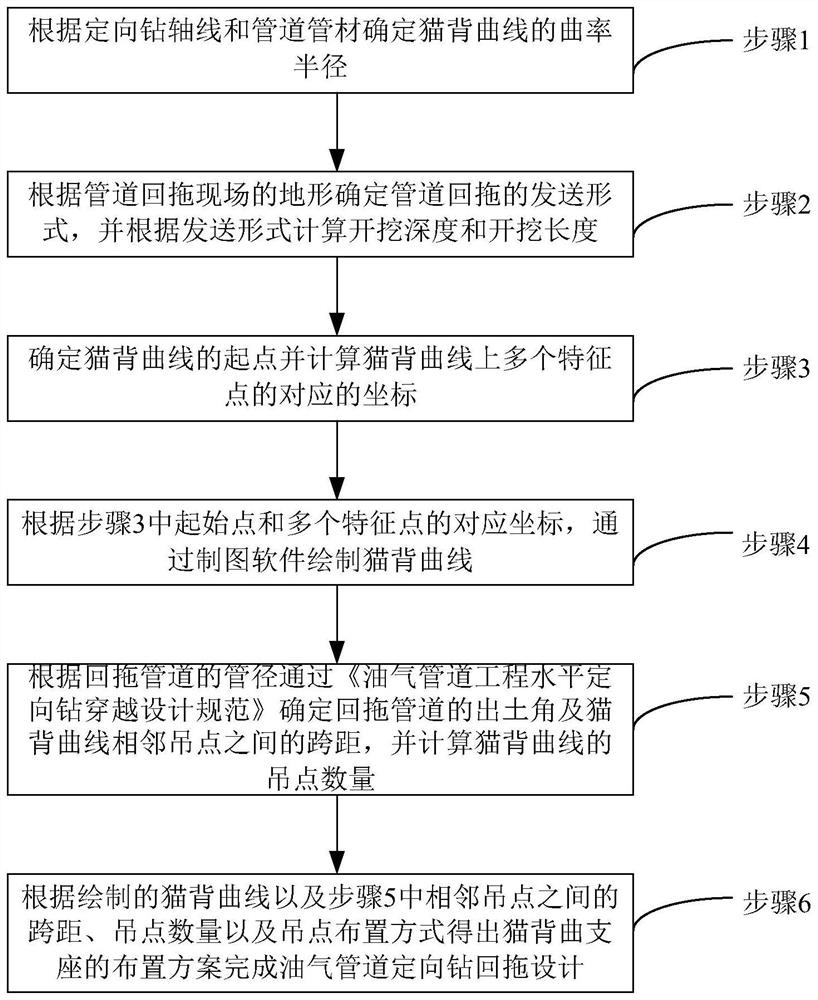
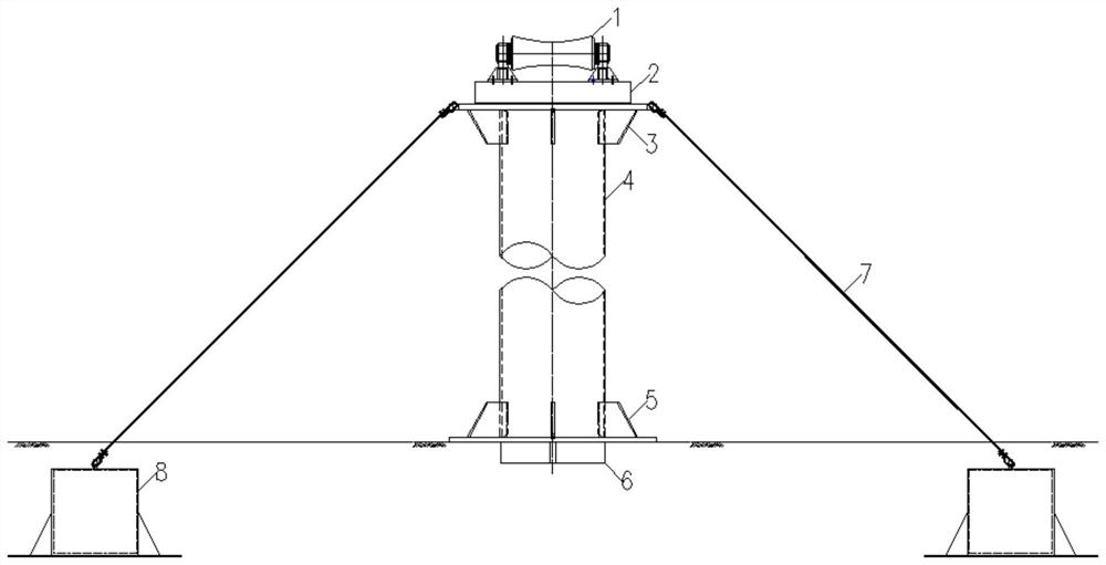
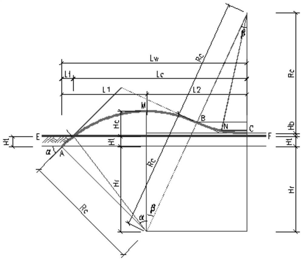
The invention discloses an oil and gas pipeline directional drilling back-dragging design method. The method comprises the steps: determining the curvature radius of a cat back curve according to a directional drilling axis and a pipe of a back-dragging pipeline; determining a sending form of pipeline back dragging according to topographic conditions of the pipeline back dragging construction site, and calculating the excavation depth and the length of the excavation area; determining a starting point of the cat back curve and calculating corresponding coordinates of a plurality of feature points on the cat back curve; drawing a cat back curve through cartographic software according to the corresponding coordinates of the starting point and the plurality of feature points; according to thepipe diameter of the back-dragging pipeline, determining the unearthing angle of the back-dragging pipeline and the span between the adjacent lifting points of the cat back curve through oil and gaspipeline engineering horizontal directional drilling crossing design specifications, and calculating the number of the lifting points of the cat back curve; obtaining an arrangement scheme of a cat back curve support according to the drawn cat back curve, the span between the adjacent lifting points, the number of the lifting points and the arrangement mode of the lifting points, and completing the directional drilling back-dragging design of the oil and gas pipeline.

Description

technical field [0001] The invention relates to the technical field of engineering design for directional drilling of oil and gas pipelines, in particular to a design method for directional drilling of oil and gas pipelines. Background technique [0002] In recent years, directional drilling has become more and more widely used in the field of oil and gas pipelines due to its advantages of environmental protection, safety, short construction period and low cost. Oil and gas pipeline directional drilling crossing is generally divided into three stages according to the construction process: pilot hole, reaming and pullback. Pullback is the last stage of directional drilling construction, and it is also the most critical step in directional drilling construction. [0003] As the diameter of oil and gas pipelines becomes larger and larger, the catback curve layout when the pullback pipeline enters the borehole is also lengthened, and more and more lifting points are arranged. ...

Claims


Application Information

Patent Timeline
IPC IPC(8): G06F30/17F16L1/028F16L1/06G06F113/14
CPCG06F30/17F16L1/028F16L1/06G06F2113/14
Inventor 左雷彬杨威杨春玲詹胜文李国辉马晓成王丽苏卫锋
Owner BC P INC CHINA NAT PETROLEUM CORP
Learn More