Digital image-forming tube bar material defect nondestructive flaw detection system

A digital imaging and non-destructive testing technology, applied in the analysis of materials, instruments, and analysis of solids using sound waves/ultrasonic waves/infrasonic waves, etc., can solve problems such as high technical requirements for analysts, inability to intuitively characterize defects, and insufficient intuitive display methods

Inactive Publication Date: 2008-11-19
INST OF METAL RESEARCH - CHINESE ACAD OF SCI
View PDF0 Cites 14 Cited by
  • Summary
  • Abstract
  • Description
  • Claims
  • Application Information

AI Technical Summary

Problems solved by technology

The first two can only detect defects, but cannot intuitively represent defects
In the third ultrasonic flaw detector or system, there are usually multiple detection channels, combined with the probe displacement scanning encoder and other means can realize B-scan (B-Scan) or C-scan (C-Scan) and S - Scanning (sector scanning S-Scan) and other display methods indica

Method used


Image

  • Digital image-forming tube bar material defect nondestructive flaw detection system
  • Digital image-forming tube bar material defect nondestructive flaw detection system
  • Digital image-forming tube bar material defect nondestructive flaw detection system

Examples


Embodiment 1

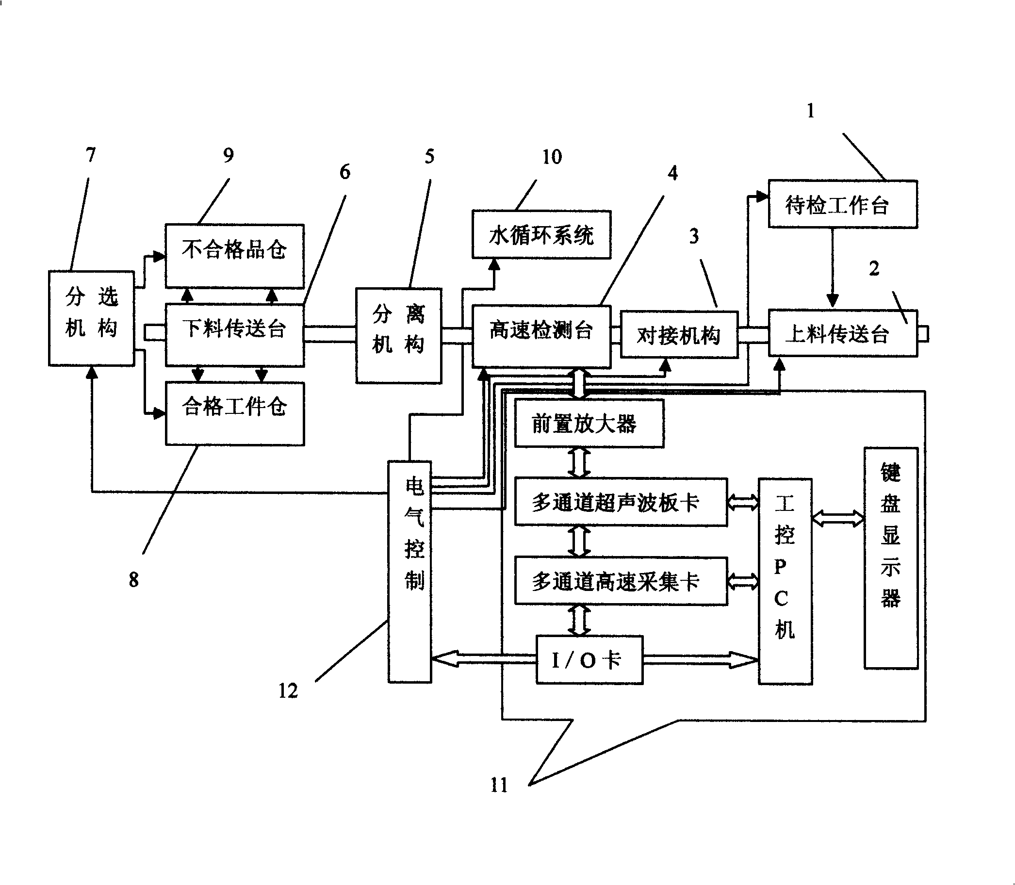
[0040] This embodiment mainly describes the ultrasonic flaw detection detection part in the pipe ultrasonic flaw detection system, a digital imaging tube rod defect non-destructive detection detection system, which is characterized in that: the digital imaging tube rod defect non-destructive detection detection system includes the workpiece to be inspected Table (1), feeding transfer table (2), docking mechanism (3), high-speed detection table (4), separation mechanism (5), unloading transfer table (6), sorting mechanism (7), qualified workpiece warehouse (8), unqualified product warehouse (9), water circulation system (10), non-destructive testing instrument system (11) and electrical control system (12);

[0041] Among them: the feeding transfer table (2) is connected with the workpiece table (1) to be inspected, the docking mechanism (3) is connected with the high-speed inspection table (4) and the feeding transfer table (2), and the high-speed inspection table (4) is connec...


PUM


Abstract

Disclosed is a detection system for nondestructive flaw detection of digital imaging tube bars, which is characterized that: the detection system for nondestructive flaw detection of digital imaging tube bars comprises a table for workpiece to be detected (1), a loading conveyer table (2), a docking mechanism (3), a high-speed detecting table (4), a disengaging mechanism (5), an unloading conveyer table (6), a separating mechanism (7), a qualified workpiece storehouse (8), an unqualified workpiece storehouse (9), a water circulation system (10), a nondestructive testing instrument system (11) and an electric control system (12). The detection system has the advantages that the sizes and locations of defects can be displayed directly according to the detection records, the conclusion can be made by simple analysis and interpretation of the displayed graphics and data, the time needed for analysis is short, and the requirements to the technical level of analysts are not high.

Description

technical field [0001] The invention relates to the technical field of non-destructive testing, and in particular provides a non-destructive testing system for digital imaging tube bar defects. Background technique [0002] In order to ensure the safety of important facilities such as various equipment, mechanical structures, and pressure vessels, and prevent catastrophic accidents, people often first think of using non-destructive testing technology to check the materials or parts involved during the manufacturing process or during the manufacturing process. Non-destructive testing is carried out during use. Especially now that the concept of damage tolerance design is popular, it is even more necessary to know exactly whether there is a defect in the workpiece, the nature of the defect, the size of the defect and the location of the defect, so as to further evaluate whether the workpiece is qualified, how dangerous it is to use, or how long its service life is. how long. ...

Claims


Application Information

Patent Timeline
IPC IPC(8): G01N35/00G01N29/04
Inventor 蔡桂喜董瑞琪陈曦张薇刘畅林青云
Owner INST OF METAL RESEARCH - CHINESE ACAD OF SCI
Why Eureka
Try Eureka