Yarn reeling machine

A yarn coiling machine and frame technology, which is applied in the field of yarn coiling machines, can solve problems such as easy shaking of the contact roller, uneven contact pressure of the package, and easy shaking

Active Publication Date: 2008-11-26
TMT MACHINERY INC
View PDF2 Cites 16 Cited by
  • Summary
  • Abstract
  • Description
  • Claims
  • Application Information

AI Technical Summary

Problems solved by technology

[0004] However, in the structure of the prior art yarn winding machine described in Japanese Patent Application Laid-Open No. 2002-338141, it is easy to shake when the touch roller moves in the up and down direction.
Therefore, it is difficult to smoothly move the touch roller up and down according to the thickness of the package, and there is a problem that the contact pressure applied to the package is uneven.
In addition, in the retracting mechanism of the conventional traverse device as described in Japanese Patent Application Laid-Open No. 8-301519, rattling is likely to occur during the retracting operation of the traverse device.

Method used


Image

  • Yarn reeling machine
  • Yarn reeling machine
  • Yarn reeling machine

Examples


Embodiment Construction

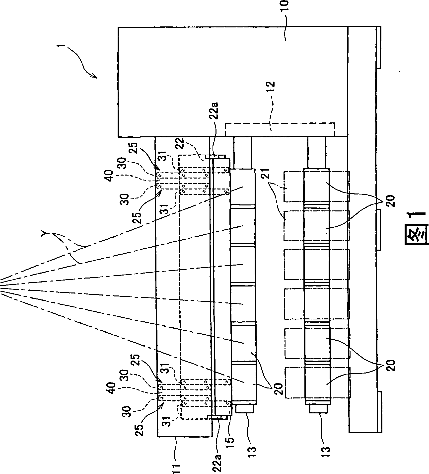
[0018] Embodiments of the present invention will be described. As shown in FIG. 1 , a plurality of (six in this embodiment) yarns Y are continuously supplied to the yarn winding machine 1 from a spinning machine not shown in the figure. The yarn winding machine 1 is configured to wind a plurality of yarns Y supplied from a spinning machine around a plurality of bobbins 20 to form a plurality of packages 21 .

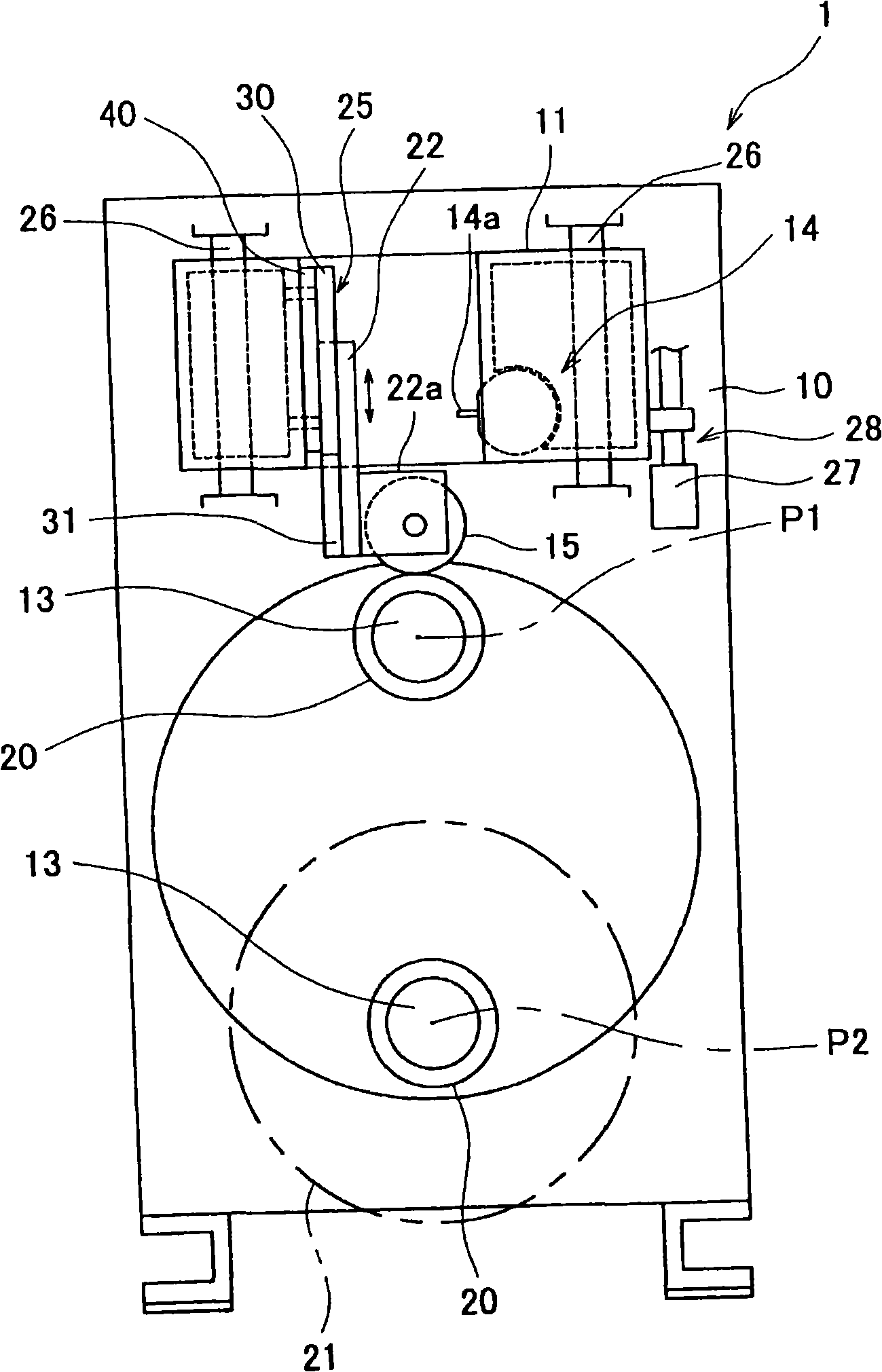
[0019] Figure 1 and figure 2 As shown, the yarn winding machine 1 includes a main frame 10, a lifting frame 11, a disc-shaped turntable 12, two bobbin holders 13, a traverse device 14, a touch roller 15, and the like. The lifting frame 11 is provided on the main body frame 10 so as to be movable (liftable) in the vertical direction. The turntable 12 is rotatably provided on the main frame 10 . The bobbin rack 13 is supported on the main body frame 10 through the turntable 12, and a plurality of bobbin tubes 20 are mounted thereon. The traversing device 14 is a device...


PUM


Abstract

The invention provides a yarn reeler, causing a contact roller to move swimmingly corresponding to the thickness of a package, and restraining disproportionation of the contact pressure applied on the package. The yarn reeler (1) comprises a spool stand (13) supported on a frame (10) of a main body, and equipped with a barrel (20); a lifting frame (11) movably supported on the frame (10) of the main body along the vertical direction; a contact roller (15), arranged in parallel with the spool stand (13) and contacted with a cirumferential surface of the package (21) with the barrel (20) or formed on the barrel (20); a supporting plate (22), movably supported on the lifting frame (11) along the vertical direction for rotating freely to support the contact roller (15); a guide unit (25) for guiding the supporting plate (22), along the vertical direction relative to the lifting frame (11).

Description

technical field [0001] The present invention relates to a yarn winding machine for winding continuously supplied yarn. Background technique [0002] Conventionally, there is known a yarn winding machine that winds a yarn continuously supplied from a spinning machine or the like to a bobbin mounted on a bobbin holder. Such a yarn winding machine is generally equipped with a contact device that applies a predetermined contact pressure to the package formed on the bobbin by rotating while contacting the yarn layer wound on the bobbin in a state parallel to the bobbin holder. roll. [0003] The contact roller is configured to be able to move up and down in contact with the package according to the thickness of the package, so that even if the diameter of the package increases when the wire is wound on the bobbin, a certain force can be applied to the package. contact pressure. For example, in the yarn winding machine described in Japanese Patent Application Laid-Open No. 2002...

Claims


Application Information

Patent Timeline
IPC IPC(8): B65H54/52B65H54/02
CPCB65H54/52B65H67/048B65H67/056B65H2701/31
Inventor 桥本欣三
Owner TMT MACHINERY INC
Why Eureka
Try Eureka