Centrifugal blower with backward inclined blade wheel

A backward vane and vane wheel technology, which is applied to the components of pumping devices for elastic fluids, mechanical equipment, machines/engines, etc. Saving energy is not economical and other issues, to achieve the effect of reducing friction loss

Inactive Publication Date: 2008-11-26
株式会社泰拉尔极东
View PDF5 Cites 6 Cited by
  • Summary
  • Abstract
  • Description
  • Claims
  • Application Information

AI Technical Summary

Problems solved by technology

However, individual correspondence brings about an increase in weight or processing
Moreover, the increase in the weight of the blade wheel

Method used


Image

  • Centrifugal blower with backward inclined blade wheel
  • Centrifugal blower with backward inclined blade wheel
  • Centrifugal blower with backward inclined blade wheel

Examples


Embodiment Construction

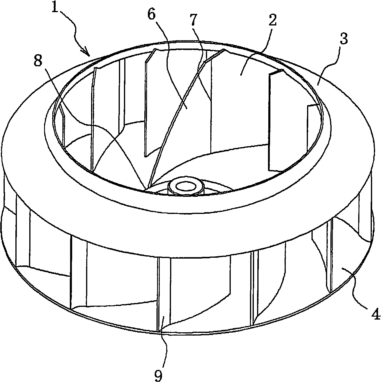
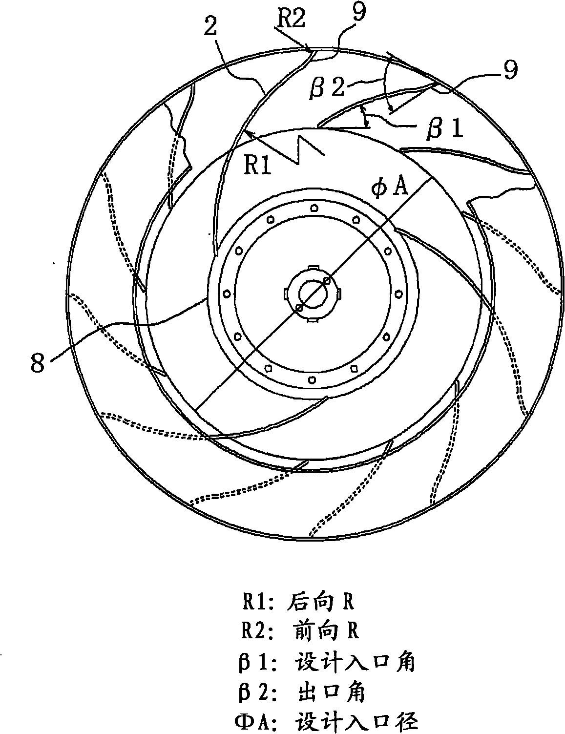
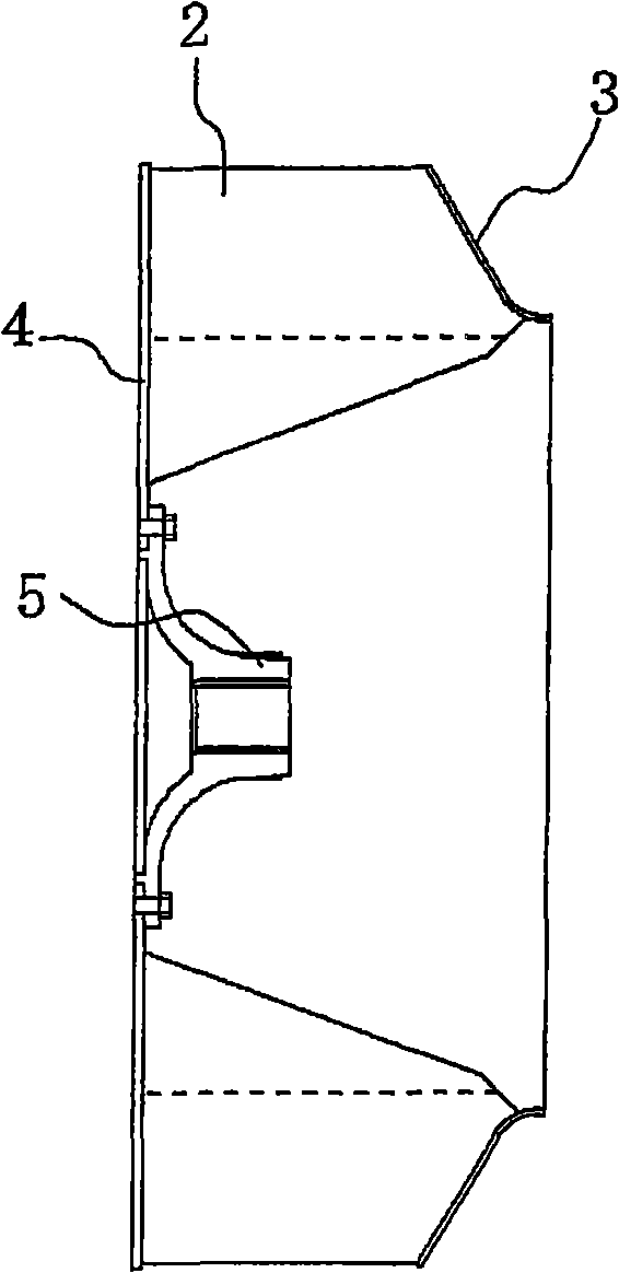
[0020] Fig. 1 shows a schematic diagram of an embodiment of the blade wheel of the centrifugal blower of the present invention, Fig. 2 is a plan view, and Fig. 3 is a cross-sectional view. The backward vane wheel 1 is composed of a vane plate 2, a shroud 3, an impeller disk 4, and an impeller shaft 5 forming vane pieces. The blade plate 2 is arranged at equal intervals around the circumference between the shroud 3 of the blade wheel 1 and the impeller disk 4, and every three of the blade plates 2 group, the slightly triangular extension 6 is formed from the blade The front edge portion 7 of the plate 2 is curved forward in a streamline shape along the direction of rotation, and is provided so that the front end portion reaches the inner edge portion 8 of the blade wheel 1.

[0021] The shape of the curved portion of the blade plate 2 having the extension 6 is shown in FIG. 2 as being curved backward (curvature R1) with respect to the rotation direction of the blade wheel. The blad...


PUM


Abstract

The invention aims at providing a centrifugal blower with a back vane wheel, which can reduce the loss of conflict and try for improving the performance of the blower. The back vane wheel of the centrifugal blower is provided with a tubular shell and a multi-wing vane wheel which can rotate freely inside the tubular shell and is supported by a shaft; a plurality of vane plates which are as long as the length of the airfoil chord from the external circumference to the central of the internal circumference of the vane wheel are arranged along the circle of the vane wheel an equal intervals; besides, an prolonging part in an approximate triangle shape is arranged at the front end part of the vane plate by spaced by a plurality of the vane plates; wherein, the prolonging part bends in a streamline shape to the front along the rotating direction and the front end part of the prolonging part is led to reach the inner edge part of the vane wheel. Besides, the multi-wing vane wheel is formed by leading the end part of the vane plate at the external circumference of the vane wheel to deform along the rotation direction of the vane wheel.

Description

Technical field [0001] The present invention relates to a centrifugal blower with a backward blade wheel used as a variety of air supply and exhaust equipment, painting equipment, dust collection equipment, and ventilation equipment in factories. Background technique [0002] The backward blade wheel of the centrifugal blower makes the outlet part of the blade plate face the radial direction, and the outlet angle of the blade plate faces the rear (30°-60°), and the blade plate formed in a curve from the inlet part to the outlet part is along the A plurality of the blade wheels are arranged at equal intervals along the circumference of the blade wheel. In this case, as illustrated in Fig. 4, a plurality of blade plates having the same chord length are mounted between the main plate and the side plate, and driving force is applied to rotate the blade wheel. The fluid is sucked from the blade wheel axis direction to the blade plate inlet, and the pressure is boosted by the blade pla...

Claims


Application Information

Patent Timeline
IPC IPC(8): F04D29/30
Inventor 永井秀满藤井繁满
Owner 株式会社泰拉尔极东
Why Eureka
Try Eureka