Vehicular obstacle detection device capable of indicating obstacle distance

An obstacle detection and obstacle technology, applied in the direction of measuring devices, using re-radiation, photo interpretation, etc., can solve the problem of not being able to know the relative relationship between the rear of the car and the obstacle, and not being able to obtain the image formula representing the distance from the obstacle concept and other issues to achieve the effect of reducing the chance of collision

Inactive Publication Date: 2008-11-26
李世雄
View PDF0 Cites 15 Cited by
  • Summary
  • Abstract
  • Description
  • Claims
  • Application Information

AI Technical Summary

Problems solved by technology

[0004] When the above-mentioned reversing radar device is used, it is still impossible to know the relative relationship between the rear of the car and the obstacle. Although the digital information representing the distance has been presented on the display, it is only a digital presentation for the driver and cannot be viewed from the screen. The image concept representing the distance from the obstacle can be obtained directly on the computer, so the digital concept must be converted into the actual distance concept again

Method used


Image

  • Vehicular obstacle detection device capable of indicating obstacle distance
  • Vehicular obstacle detection device capable of indicating obstacle distance
  • Vehicular obstacle detection device capable of indicating obstacle distance

Examples


Embodiment Construction

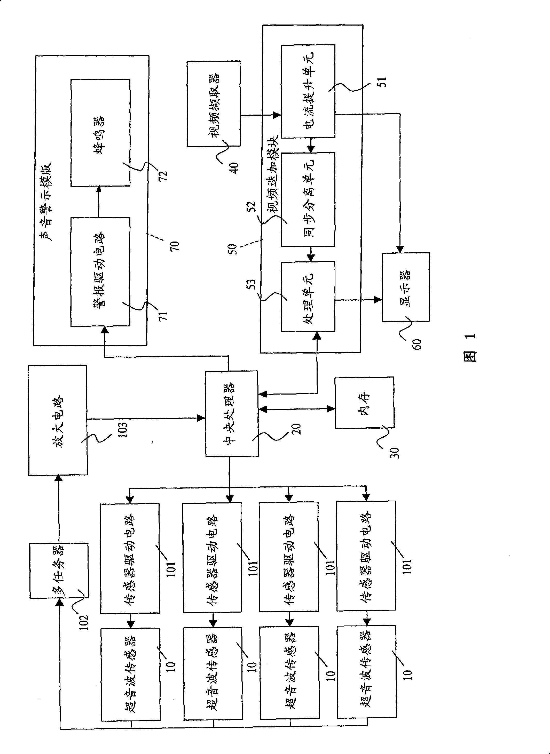
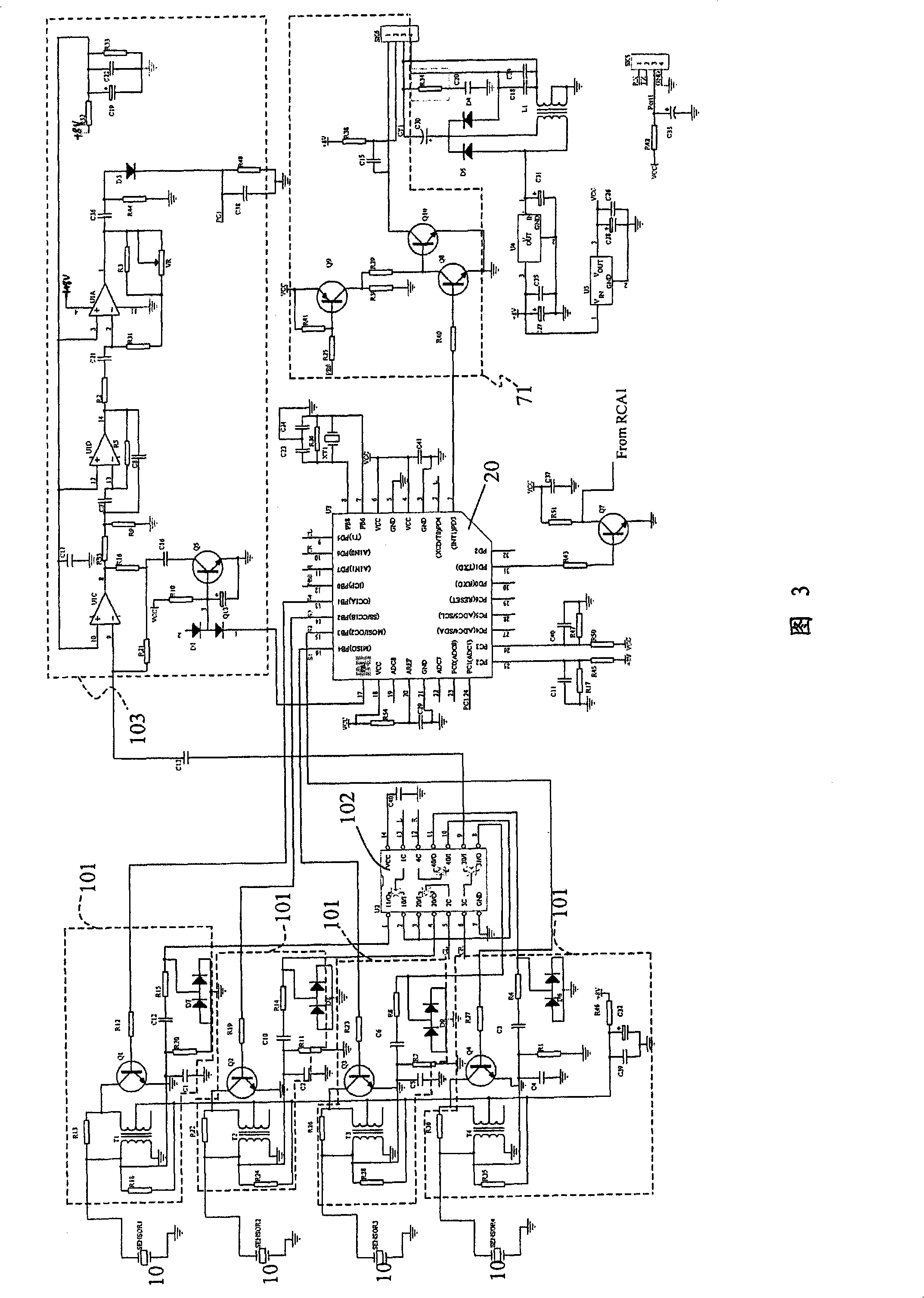
[0031] About a preferred embodiment of the present invention, please refer to shown in Fig. 1, comprise a plurality of ultrasonic sensors 10, central processing unit 20, a plurality of sensor driving circuits 101, multiplexer 102, amplifying circuit 103, memory 30, video The capture device 40 , the video superposition module 50 , the display 60 and the sound alarm module 70 .

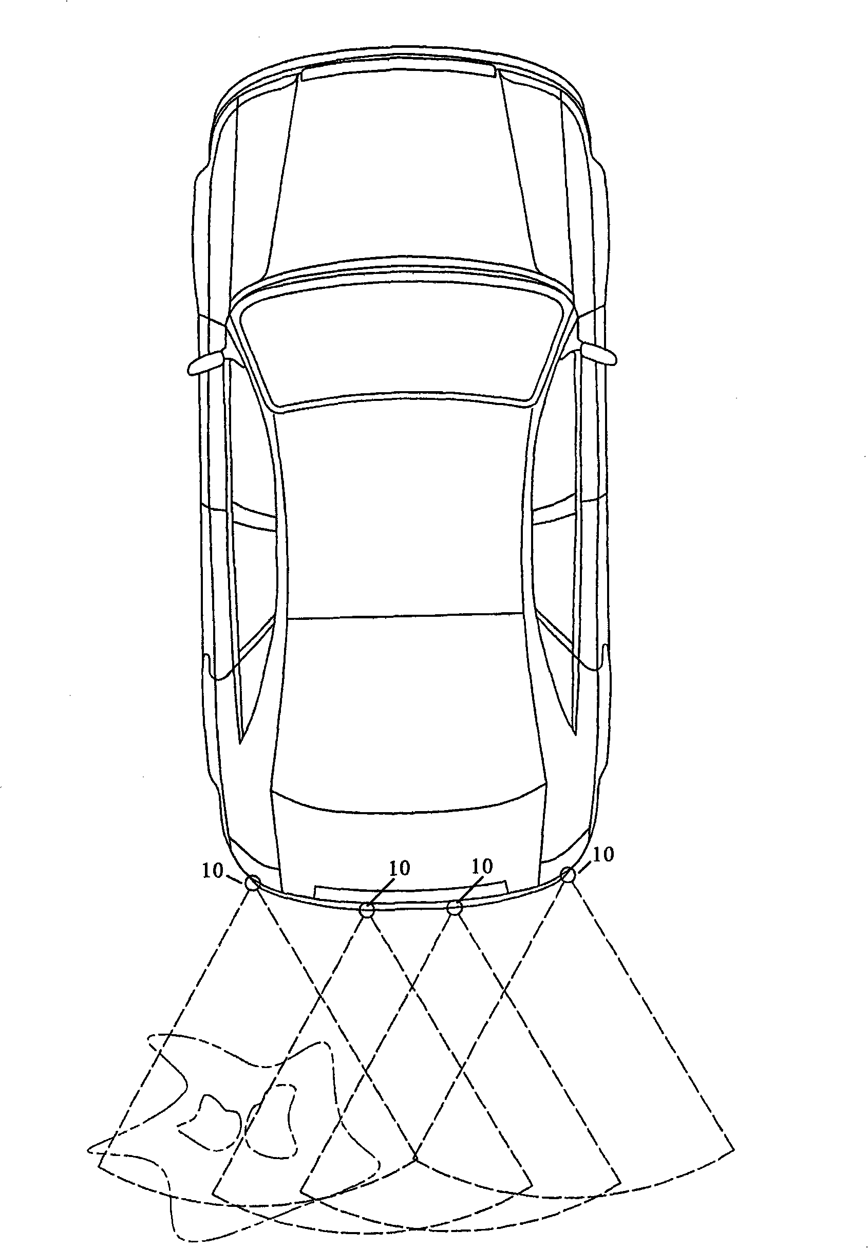
[0032] see figure 2 As shown, each ultrasonic sensor 10 is arranged at the rear of the vehicle and is used to emit ultrasonic signals. When there is an obstacle on the transmission route of the ultrasonic signal, the ultrasonic signal will be reflected by the obstacle and received by the ultrasonic sensor 10. And output a coordinate calculation signal according to the reflected ultrasonic signal.

[0033] The central processing unit 20 is connected to and controls the aforementioned plurality of ultrasonic sensors 10, and calculates the time interval between the ultrasonic sensors 10 sending and receiv...


PUM


Abstract

The invention relates to a vehicle obstruction testing device used for dropping a hint of obstruction distance. A plurality of store fields are divided in the memory of the device. The store fields respectively correspond to position coordinates that ultrasonic signals can reach. And then, the ultrasonic signals are analyzed by a CPU to calculate the position coordinate data of the obstruction. Status data that means whether the obstruction exits or not is filled into the store field. Afterwards, a corresponding section is divided by a video image superposition module in a video image captured by a video image capture according to the position coordinate represented by every store field. The corresponding section is matched with the position of an ultrasonic sensor and the status data of store field memory, so as to lead a display to show the image superposed by the video image of an ultrasonic transmission path and the video image captured by the video image capture.

Description

technical field [0001] The invention relates to a vehicle obstacle detection device, in particular to a vehicle obstacle detection device which can indicate the obstacle distance. Background technique [0002] Today, as technology is more and more developed, the reversing radar has almost become the basic equipment of the car. Generally, the reversing radar is installed with an ultrasonic sensor at the rear of the car. When the reversing file is entered, the ultrasonic sensor is activated to emit ultrasonic signals. When the ultrasonic signal encounters an obstacle, it will turn back and be received by the ultrasonic sensor, and then use the sound alarm installed in the car to prompt and convey the obstacle information to the driver, thereby assisting the driver to complete the parking process smoothly. [0003] At present, there is a better reversing radar device on the market, which further uses a camera to take pictures of the rear, and then presents the rear images on th...

Claims


Application Information

Patent Timeline
Patent Type & Authority Applications(China)
IPC IPC(8): G01S15/08G01C11/04
Inventor 李世雄
Owner 李世雄
Why Eureka
Try Eureka