

Halide scavengers for high temperature applications
A technology of adsorbent and alumina, which is applied in the field of preparation of adsorbent, preparation of HCl in synthesis gas, and treatment of gas and liquid flow, which can solve the problems of low BET surface area, unusable scavenger, insufficient high carrying capacity, etc.
- Summary
- Abstract
- Description
- Claims
- Application Information
AI Technical Summary
Problems solved by technology
Method used
Image

Examples
Embodiment 1
[0021] The four-legged rotating disk is used as a forming device, and a 0.5lbs (0.227kg)-0.6lbs (0.272kg) / min Powder, 0.9 lbs (0.408 kg) - 1.2 lbs (0.544 kg) / min of A-300 alumina powder and 0.3 lbs (0.136 kg) - 0.7 lbs (0.318 kg) / min of water were fed continuously. Some granulated alumina was placed in the pan as a seed before the formation process started. Product beads were collected and aged overnight at ambient conditions. Afterwards, the 5 x 8 sieved portion was activated in an air circulating oven at 400°C. Samples labeled as samples 1, 2 and 3 were prepared by varying the feed ratio and formation conditions. An additional sample labeled 4 was prepared by using sodium acetate solution instead of water as the sintering liquid. Table 2 lists all the selected properties of the samples used.
[0022] Table 2
[0023] sample
Embodiment 2
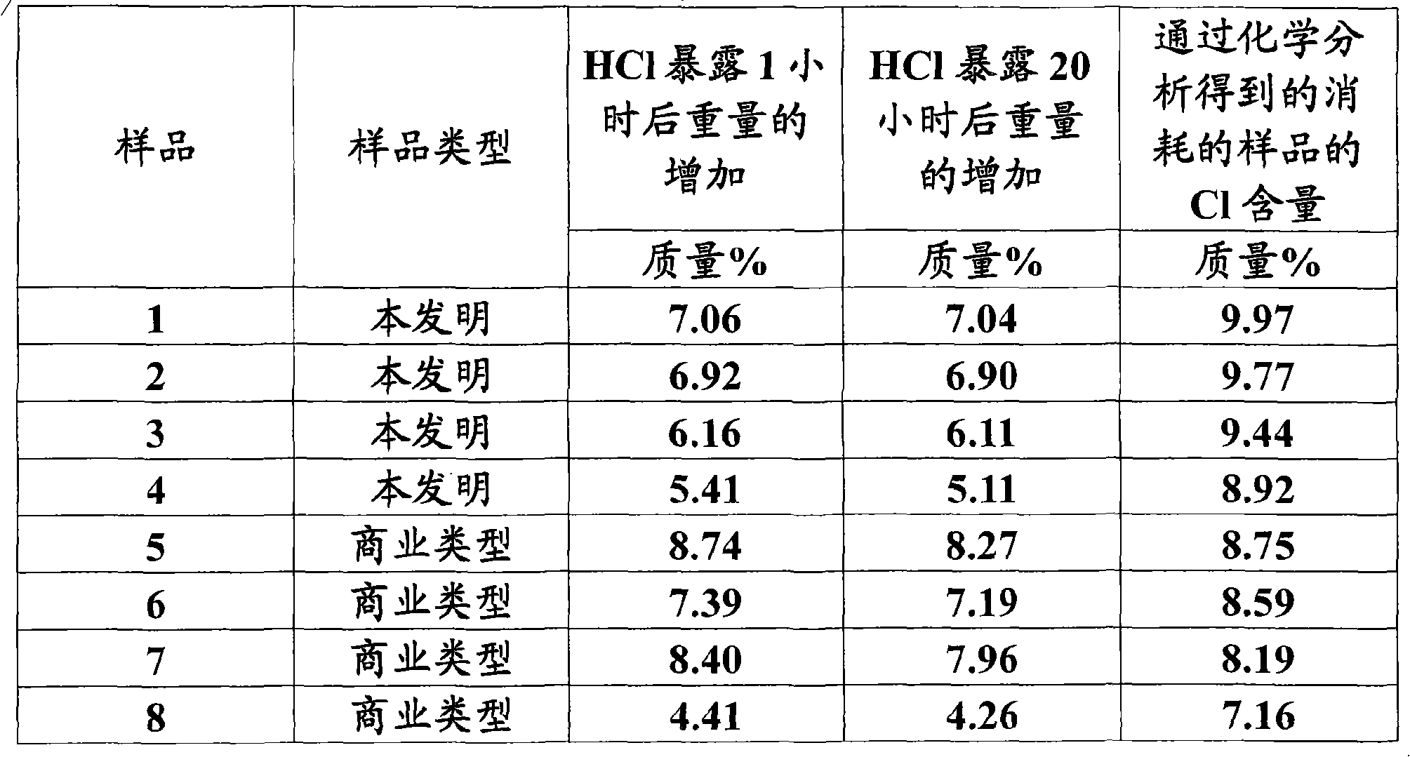
[0025] The HCl removal capacity of samples prepared according to the present invention was first measured in a McBain apparatus consisting of a glass manifold to which eight glass spring balances were attached. Each of these compartments can be heated individually, and all samples added to the balance's small basket can be evacuated and thereafter exposed to 5 torr of HCl pressure for up to 24 hours. The weight gain due to the acquisition of HCl was then measured. The pressure control system kept the pressure constant during the experiment and quickly replenished the depleted HCl. Finally, samples consumed from the McBain apparatus were analyzed to determine Cl retention.
[0026] Table 3 summarizes test data for samples of the invention and some reference samples. All samples were first activated in vacuo at 315°C, followed by experiments to obtain HCl at 288°C. Samples 5-8 are commercial products from four different suppliers.
[0027] table 3
[0028]
[0029] The d...
Embodiment 3
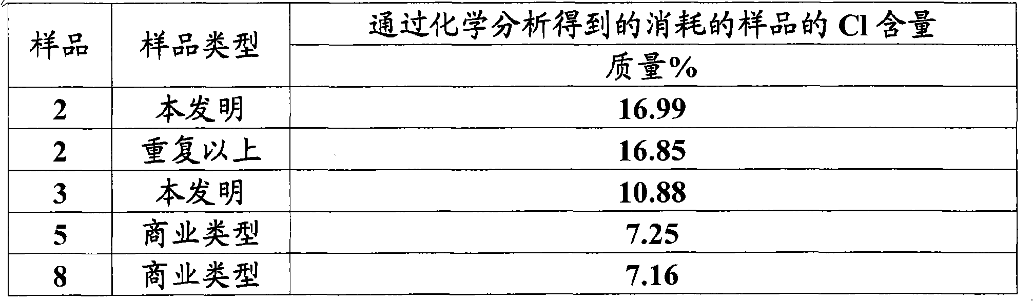
[0031] The data in Example 2 were obtained under stable conditions which are not typically typical for industrial applications. Therefore, selected samples were compared in experiments to obtain flow of HCl. In each case the 55cm 3 The sample is injected into the tubular reactor (2.54cm diameter), and the gaseous mixture of nitrogen mixed with 1 vol% HCl flows at 550cm 3 / min flow through the bed until a critical point (BT) occurs in the HCl, measured by the change in pH of a standard NaOH solution placed at the outlet of the fluid. The bed was then purged with pure nitrogen, cooled and the spent particles distributed in 5 separate bed sections were chemically analyzed to determine Cl loading. Samples were treated at 315°C in pure nitrogen for at least 1 hour prior to absorption of HCl experiments.
[0032] Table 4 shows the obtained values of Cl determined from BT experiments by analysis of consumed samples.
[0033] Table 4
[0034]
[0035] Table 4 provides eviden...
PUM
| Property | Measurement | Unit |
|---|---|---|
| specific surface area | aaaaa | aaaaa |
Abstract
Description
Claims
Application Information