
Plastics injection-moulding machine with integrated, linear-rotary direct driv

An injection molding machine and linear drive technology, applied to synchronous motors with stationary armatures and rotating magnets, electromechanical devices, electric components, etc., can solve problems such as complex control methods, improve dynamic response, and improve mechanical stability Effect

Active Publication Date: 2008-11-26
SIEMENS AG
View PDF0 Cites 22 Cited by
  • Summary
  • Abstract
  • Description
  • Claims
  • Application Information

AI Technical Summary

Problems solved by technology

The disadvantage of this type of drive is, on the one hand, that its control is quite complicated, because when controlling the two rotary motors to achieve linear motion, the threaded transmission must also be considered
The large structure of the entire drive is also a disadvantage of this drive

Method used


Image

  • Plastics injection-moulding machine with integrated, linear-rotary direct driv
  • Plastics injection-moulding machine with integrated, linear-rotary direct driv
  • Plastics injection-moulding machine with integrated, linear-rotary direct driv

Examples


Embodiment Construction

[0016] The examples to be described in detail below are preferred embodiments of the present invention.

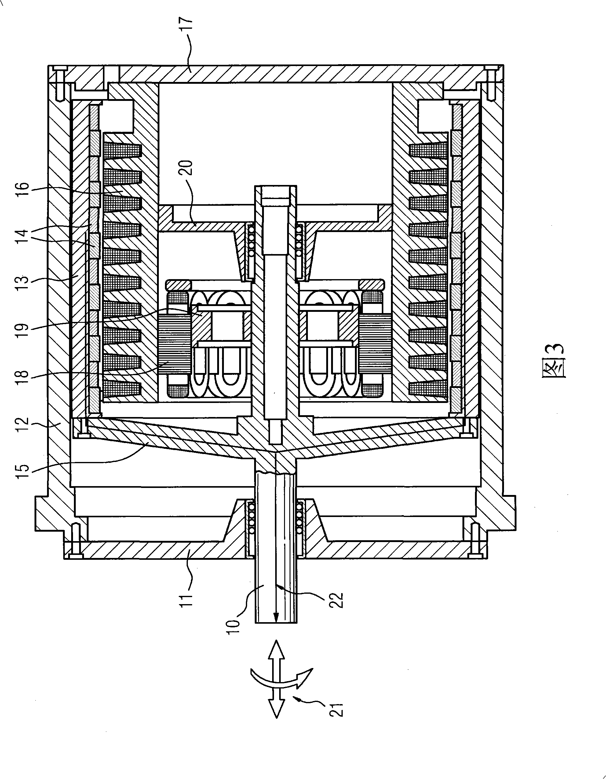
[0017] The built-in linear-rotary electric direct drive shown in a sectional view in FIG. 3 has an output shaft 10 whose output end is supported on a load-bearing part 11 of a housing 12 . Inside the casing 12, a rotationally symmetrical pot-shaped structure is formed on the output shaft 10, and this pot-shaped structure is the outer rotor 13 of the linear direct drive device. A plurality of permanent magnets 14 are arranged on the inner wall of the cylindrical section of this outer rotor. The end cap 15 establishes the connection between the cylindrical outer rotor section 13 and the output shaft 10 .

[0018] The hollow cylindrical stator 16 of the linear motor is located inside the outer rotor 13 . The stator 16 is connected to a cover plate 17 located on the opposite side of the load-bearing member 11 , and the cover plate 17 is screwed on the casing 12 . The stator...


PUM


Abstract

A plastics injection-moulding machine is to be equipped with a more compact drive that undergoes less wear. For this purpose, it is envisaged to integrate the direct rotational drive into the direct linear drive. Accordingly, the electric linear motor has a pot-shaped external rotor (13), in the inner space of which the main part of a hollow-cylindrical stator (16) of the linear motor is arranged and which is firmly connected to the output shaft (10). The rotary drive has a stator (18), which is mounted on the inner wall of the hollow-cylindrical stator (16) of the linear motor, and a rotor, which is firmly coupled to the output shaft (10) within the stator (18) of the rotary electric motor. This direct drive produces a very compact type of construction and it is possible to dispense with easily wearing threaded spindles.

Description

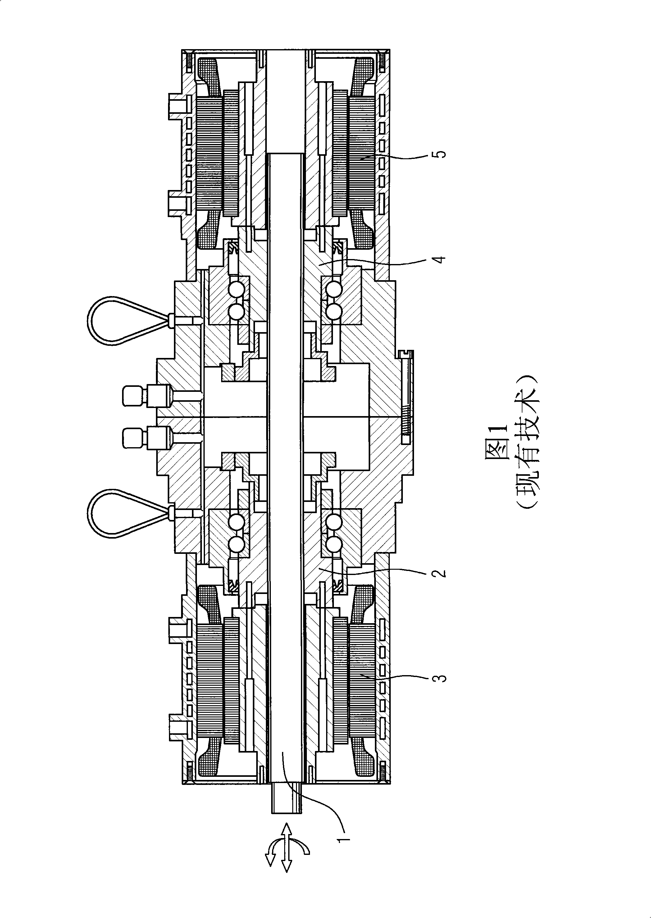
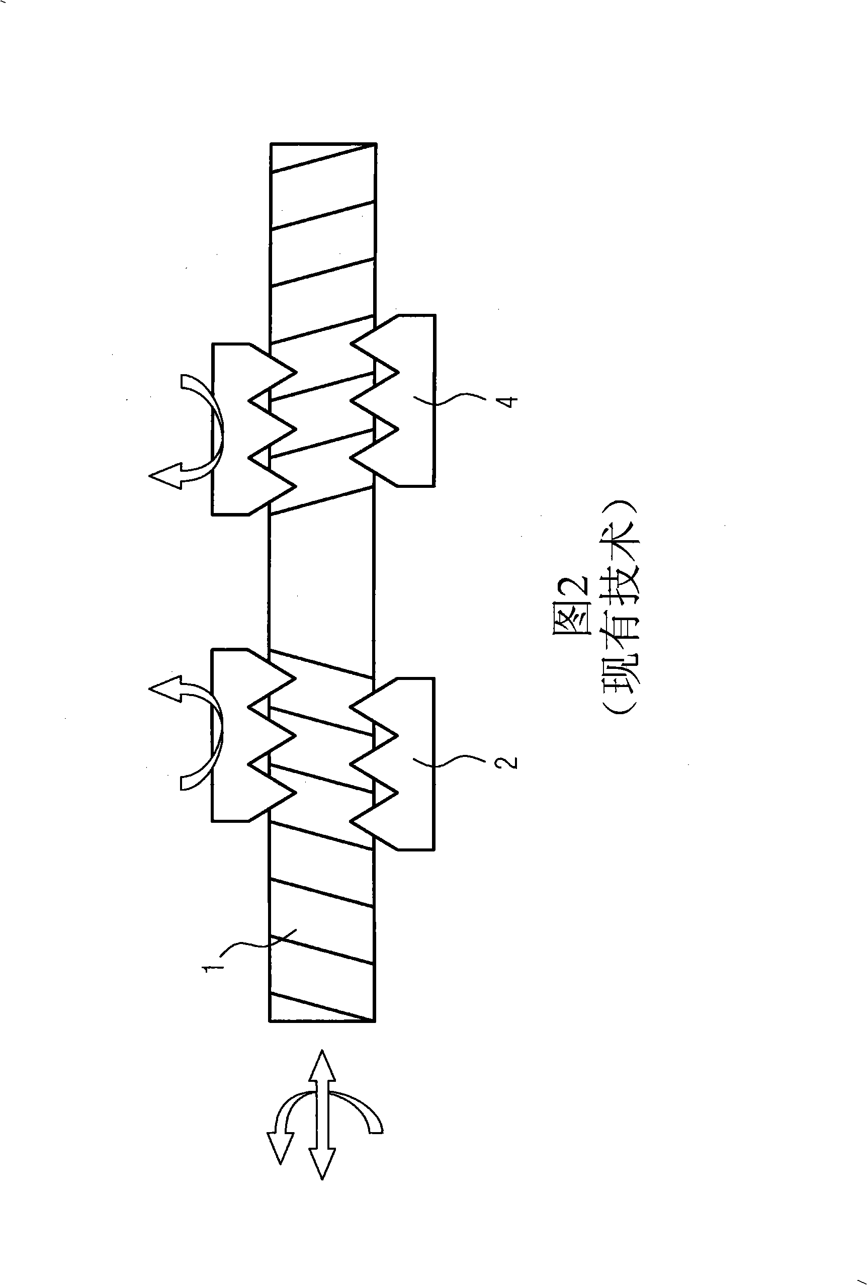
technical field [0001] The invention relates to a plastic injection molding machine with an electric rotary drive and an electric linear drive. Background technique [0002] Drives in plastic injection molding machines or similar machines, especially injection and dosing units, require rotary and linear motion on the drive shaft. These movements must occur independently, but sometimes overlap. [0003] Conventional technology achieves this movement with two degrees of freedom by using two rotary drives separated from each other. Figure 1 illustrates such a drive in cross section. The threaded spindle 1 is driven by a first rotary drive device 3 via a first spindle nut 2 and by a second rotary drive device 5 via a second spindle nut 4 . Threaded spindle 1 is used to convert rotary motion into linear motion. The principle of operation can be explained by FIG. 2 , which shows a schematic view of the output shaft (Abtriebswelle) or threaded spindle 1 and spindle nuts 2 , 4 ....

Claims


Application Information

Patent Timeline
Patent Type & Authority Applications(China)
IPC IPC(8): B29C45/50
CPCB29C2045/1793H02K2201/18H02K41/03H02K21/14B29C2045/1792H02K16/025B29C45/5008
Inventor 托马斯·巴德迈克海洛·托尔多诺夫
Owner SIEMENS AG
Learn More