Machining robot control apparatus

A technology for control devices and robots, applied in automatic control devices, metal processing machinery parts, feeding devices, etc., can solve problems such as inability to correct robots correctly

Inactive Publication Date: 2008-12-03
FANUC LTD
View PDF1 Cites 28 Cited by
  • Summary
  • Abstract
  • Description
  • Claims
  • Application Information

AI Technical Summary

Problems solved by technology

Therefore, in the control device disclosed in Japanese Patent Laid-Open No. 2005-125427 and Japanese Patent No. 2718688, a situation in which the position of the robot cannot be correctly corrected also occurs.

Method used


Image

  • Machining robot control apparatus
  • Machining robot control apparatus
  • Machining robot control apparatus

Examples


Embodiment Construction

[0030] Embodiments of the present invention will be described below with reference to the drawings. In the following drawings, the same reference signs are attached to the same members. For easy understanding, the scales of these drawings are appropriately changed.

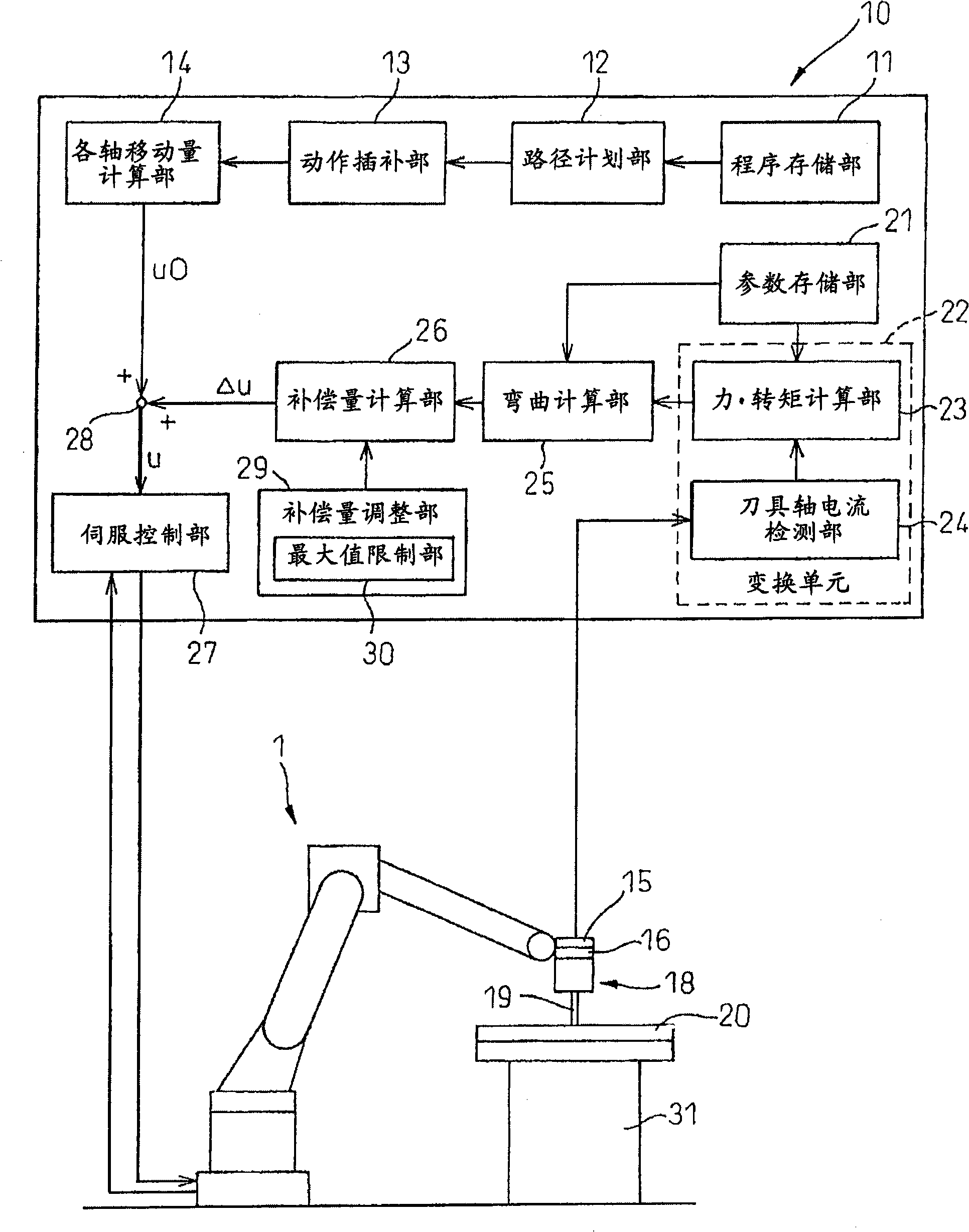
[0031] figure 1 is a functional block diagram of the control device of the processing robot according to the present invention. Such as figure 1 As shown, a control device 10 is connected to a robot 1 , for example, a vertical articulated robot with a six-axis structure. A knife 18 is attached to the tip of the arm of the robot 1 . exist figure 1 In , the tool 18 is a tool used in friction welding and includes an action part 19 . The action part 19 contacts the workpiece 20 fixed on the support table 31 to process the workpiece 20 . In addition, the cutter 18 may also be of other structures, such as a grinder.

[0032] As shown in the figure, a six-axis force sensor 15 is disposed between the tool 18 and t...


PUM


Abstract

A control apparatus (10) for a machining robot (1) adapted to machine a workpiece (20) by coming into contact with an effector (19) of a tool (18) attached to the machining robot with the workpiece comprises: detecting means (15) for detecting a force or moment acting between the effector of the tool and the workpiece; converting means (22) for converting the force or moment detected by the detecting means into a force or moment acting on the joint axis of the machining robot; deflection calculating means (25) for calculating a deflection occurring at the joint axis of the machining robot on the basis of the force or moment acting on the joint axis of the machining robot and obtained from the converting means; ; and correcting means (28) for correcting at least one of a position command or a speed command for the joint axis of the machining robot in such a manner as to compensate for the deflection calculated by the deflection calculating means. Accordingly, the position of the robot is accurately corrected without being affected by the deflection of the joint axis.

Description

technical field [0001] The invention relates to a control device for a multi-joint robot. In particular, the present invention relates to a control device for a processing robot that performs processing such as friction welding or grinding on a workpiece. Background technique [0002] Traditionally, workpieces have been machined using tools mounted on articulated robots. In such work, it is desirable to avoid applying excessive force to the workpiece by checking in advance the state where the tool is in contact with the workpiece. [0003] In the control devices disclosed in Japanese Patent Laid-Open No. 2005-125427 and Japanese Patent No. 2718688, the position of the robot is corrected in the work coordinate system in order to avoid applying excessive force to the workpiece. The control devices disclosed in JP-A-2005-125427 and Japanese Patent No. 2718688 are used when the tool movement of the robot is relatively small, such as spot welding or seam welding. [0004] Howe...

Claims


Application Information

Patent Timeline
Patent Type & Authority Applications(China)
IPC IPC(8): B25J9/16B25J9/10B25J13/08B23Q15/00
CPCB25J9/1638B25J9/1633
Inventor 二瓶亮加藤哲朗黑下彰喜
Owner FANUC LTD
Why Eureka
Try Eureka