Tool path display apparatus

一种显示装置、刀具轨迹的技术,应用在仪器、计算机控制、模拟器等方向,能够解决无法分析形状误差等问题

Active Publication Date: 2013-03-06
FANUC LTD
View PDF4 Cites 10 Cited by
  • Summary
  • Abstract
  • Description
  • Claims
  • Application Information

AI Technical Summary

Problems solved by technology

[0009] Furthermore, in Japanese Patent Application Laid-Open No. 2009-98982, although a technique for displaying acceleration on a simulated tool path is disclosed, it does not display acceleration etc. on an actual tool path.
Therefore, in Japanese Patent Application Laid-Open No. 2009-98982, it is impossible to analyze the shape error corresponding to the actual processed surface.

Method used


Image

  • Tool path display apparatus
  • Tool path display apparatus
  • Tool path display apparatus

Examples


Embodiment Construction

[0028] Embodiments of the present invention will be described below with reference to the drawings. In the following drawings, the same reference symbols are assigned to the same components. For easy understanding, the scales of these drawings are appropriately changed.

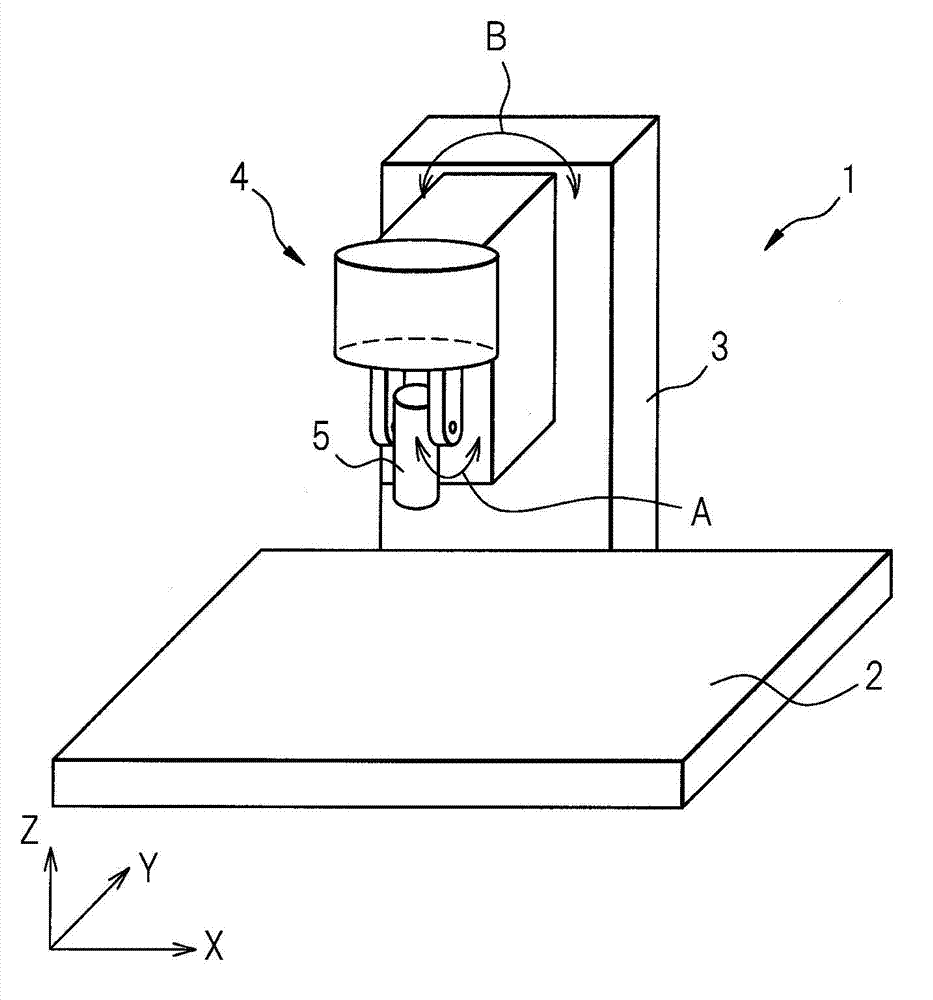
[0029] figure 1 It is a perspective view of a machine tool equipped with a tool path display device according to the present invention. figure 1 The machine tool 1 shown as an example in the figure is a 5-axis processing machine. The machine tool 1 includes a table 2 on which a workpiece (not shown) is placed, and a column 3 relatively movable in three directions (X axis, Y axis, Z axis) perpendicular to each other with respect to the table 2 . As shown, a machining head 4 extends transversely from the column 3 , the machining head 4 rotating about a B-axis parallel to the surface of the table 2 . Furthermore, a tool 5 is mounted on the machining head 4 rotatably around an A-axis perpendicular to both the...


PUM


Abstract

A tool path display apparatus includes a tool coordinate value calculation unit that calculates tool commanded coordinate values and tool actual coordinate values, based on commanded value time series data of position commands for a plurality of axes, detected value time series data of position detected values for the plurality of axes, and the structure of a machine tool, an acceleration calculation unit that calculates accelerations of a tip point of a tool using the tool commanded coordinate values and the tool actual coordinate values, and a display format selection unit that selects display formats of the accelerations of the tool commanded coordinate values and the tool actual coordinate values. The display format selection unit performs at least one of color display to apply colors to the path of the tip point of the tool according to orientation and magnitude of the accelerations; vector display to display the accelerations as acceleration vectors on the path of the tip point of the tool; and connection display to display a connection that connects between end points of neighboring acceleration vectors. Therefore, the invention can easily analyze the shape error of the actual position of a drive axis or a tool against the commanded position.

Description

technical field [0001] The present invention relates to a tool trajectory display device having a display unit for acceleration or jerk of a tool tip point. Background technique [0002] Numerical controllers currently used to control machine tools sometimes have a function of displaying the trajectory of a position command and a function of displaying the trajectory of the actual movement of the tool. Specifically, the coordinates of the tip point of the tool are calculated and displayed from the time-series data of the commanded position and / or the time-series data of the actual position of the drive shaft of the machine tool. Thus, the shape error between the command trajectory of the tool tip point and the actual trajectory is analyzed visually. [0003] As an example of such prior art, Japanese Patent No. 4648471 discloses a technique of calculating the three-dimensional coordinates of the cutting edge of a tool based on the positional information of each drive shaft o...

Claims


Application Information

Patent Timeline
Patent Type & Authority Applications(China)
IPC IPC(8): G05B19/406
CPCG05B19/4069G05B2219/35349G05B19/408
Inventor 手塚淳一小川肇
Owner FANUC LTD
Why Eureka
Try Eureka