Torsion girder type hind axle

A technology of torsion beam and rear axle, applied in the field of auto parts, can solve the problems of increased use cost, increased wind resistance and fuel consumption, and reduced space utilization rate, etc. Effect

Inactive Publication Date: 2008-12-03
CHERY AUTOMOBILE CO LTD
View PDF0 Cites 11 Cited by
  • Summary
  • Abstract
  • Description
  • Claims
  • Application Information

AI Technical Summary

Problems solved by technology

[0002] like figure 1 , 2 As shown, in most of the cars with torsion beam rear axles at present, the middle part of the torsion beam rear axle beam (1) adopts a structure that is convex upward and bends forward. This structure depends on changing the torsion center of the entire rear axle. To achieve the purpose of improving the fatigue life of the rear axle assembly, and then improving the service life, but the upward protrusion of the middle part of the crossbeam (1) will take up more space, so that the space utilization rate of the whole vehicle is reduced. For comfort, car manufacturers have to increase the quality and height of the vehicle, thereby increasing wind resistance and fuel consumption, and increasing the cost of use for users

Method used


Image

  • Torsion girder type hind axle
  • Torsion girder type hind axle
  • Torsion girder type hind axle

Examples


Embodiment 1

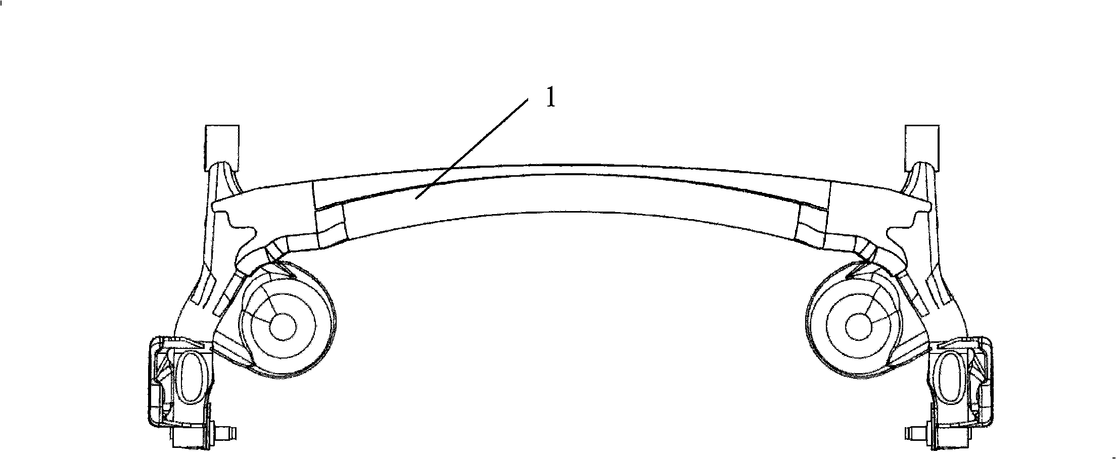
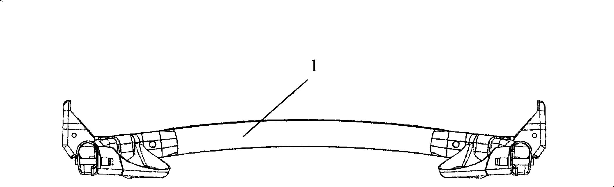
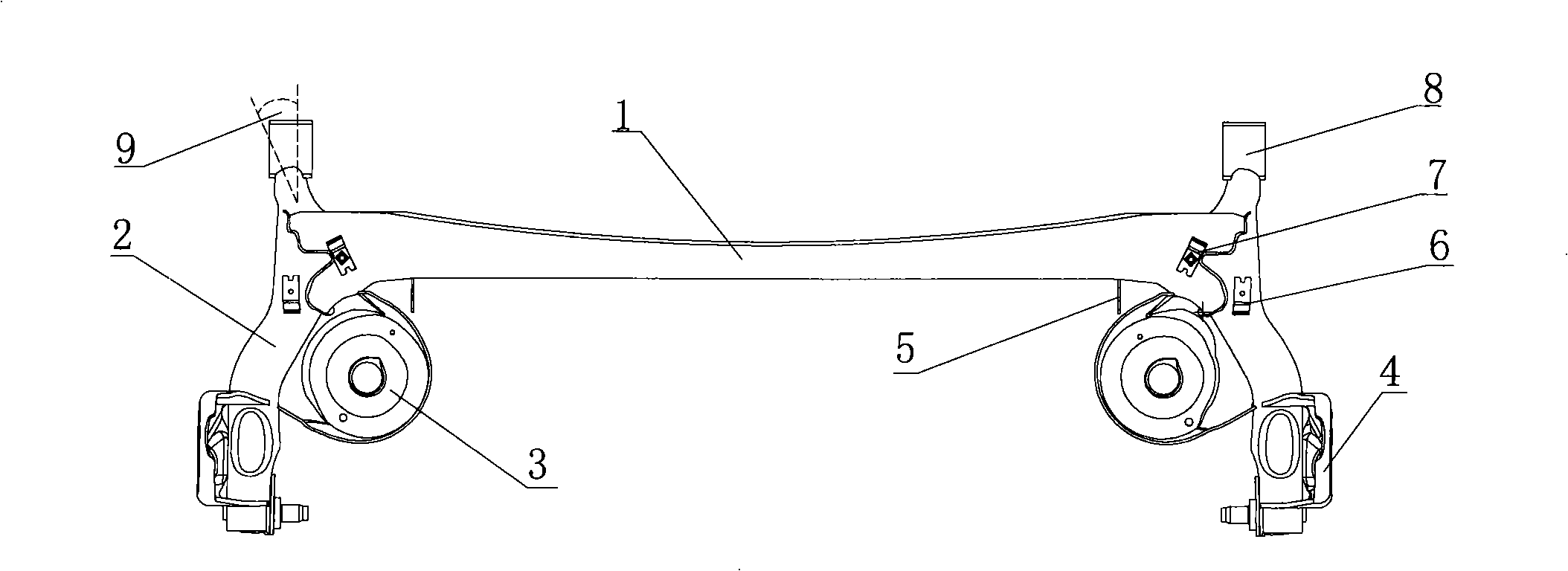
[0018] Such as image 3 , 4 As shown, the torsion beam rear axle of this embodiment includes a cross beam 1 and a suspension trailing arm 2 composed of pipes connected to the left and right ends of the cross beam 1. In particular, the top surface of the cross beam 1 is horizontal. The cross-sectional area gradually increases from the middle to the sides. The cross-sectional area of ​​the beam 1 gradually increases from the middle to the two sides, which will make the rigidity of the middle of the beam 1 relatively small, and the rigidity of the two ends are relatively large, so the high stress area connecting the longitudinal beams at the two ends of the beam 1 will be relatively weakened. , It can effectively avoid the stress concentration at the welding seam where the rear beam and the trailing arm overlap, thereby increasing the service life of the rear axle assembly. The top surface of the cross beam 1 is horizontal and does not bulge upward like a traditional cross beam, whic...


PUM


Abstract

The invention provides a twisting beam back shaft, which can guarantee the service life of the back shaft and meanwhile saves space and reduces the weight of the complete vehicle. The twisting beam back shaft of the invention comprises a beam and a pipe fitting-formed suspension trailing arm which connects to the left and right ends of the beam; in particular, the top surface of the beam is horizontal, and the cross sectional area of the beam increases gradually from the middle part to the two sides. By changing the distribution of the cross sectional area of the beam, the twisting beam back shaft of the invention can effectively avoid stress concentration at the welding seam where the back beam and the trailing arm are overlapped, and thus prolongs the service life of the back shaft assembly; the top surface of the beam is horizontal unlike the upward convex traditional beams, which can largely save the required space for arrangement, improve the space utilization of the complete vehicle, reduce the weight of the complete vehicle and fuel consumption.

Description

Technical field [0001] The invention relates to an automobile component, in particular to a torsion beam type rear axle. Background technique [0002] Such as figure 1 , 2 As shown, in most cars currently using torsion beam type rear axles, the middle part of the torsion beam type rear axle cross member (1) adopts an upwardly convex and forward curved structure, which relies on changing the torsion center of the entire rear axle To achieve the purpose of improving the fatigue life of the rear axle assembly and thereby improving the service life, but the middle part of the cross beam (1) bulges upwards will occupy more space, which reduces the space utilization rate of the entire vehicle, and ensures that the passengers in the vehicle can ride. For comfort, automobile manufacturers have to increase the quality and height of the vehicle, thereby increasing wind resistance and fuel consumption, and increasing the cost of use for users. Summary of the invention [0003] The purpose...

Claims


Application Information

Patent Timeline
Patent Type & Authority Applications(China)
IPC IPC(8): B60B35/00
CPCY02T10/86
Inventor 赵岩
Owner CHERY AUTOMOBILE CO LTD
Why Eureka
Try Eureka