Sheet takeout device

A technology for taking out devices and sheets, which is applied in the directions of transportation and packaging, thin material handling, and separation of objects, etc., can solve problems such as damage to sheets and pollution, and achieve the effect of preventing pollution and damage and preventing sliding.

Inactive Publication Date: 2008-12-03
KK TOSHIBA
View PDF1 Cites 5 Cited by
  • Summary
  • Abstract
  • Description
  • Claims
  • Application Information

AI Technical Summary

Problems solved by technology

Therefore, friction is generated between the take-out belt and the sheet, which may contaminate or damage the sheet unfavorably.

Method used


Image

  • Sheet takeout device
  • Sheet takeout device
  • Sheet takeout device

Examples


Embodiment Construction

[0034] Hereinafter, embodiments of the present invention will be described in detail with reference to the accompanying drawings.

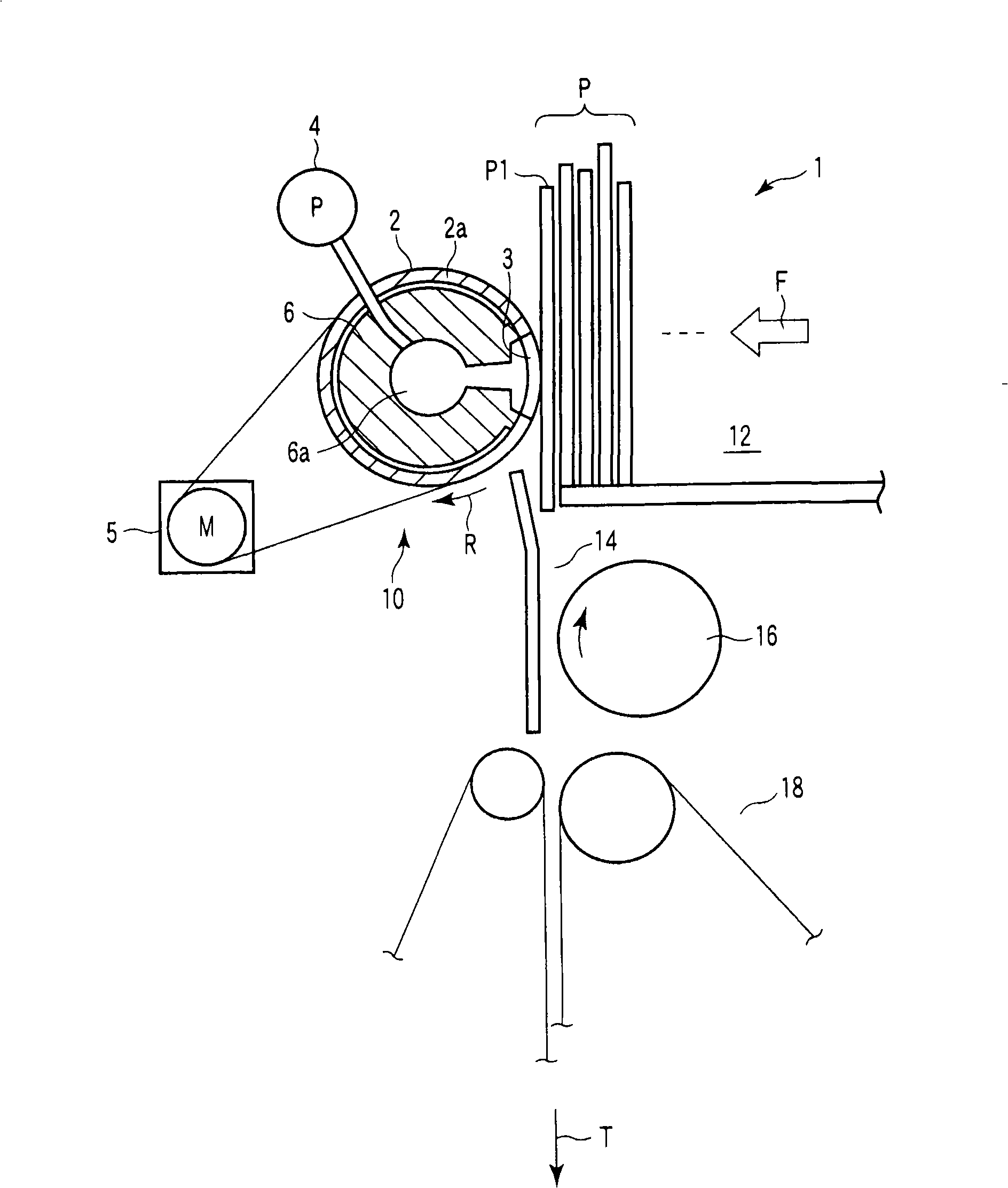
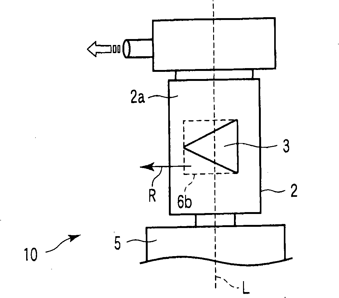
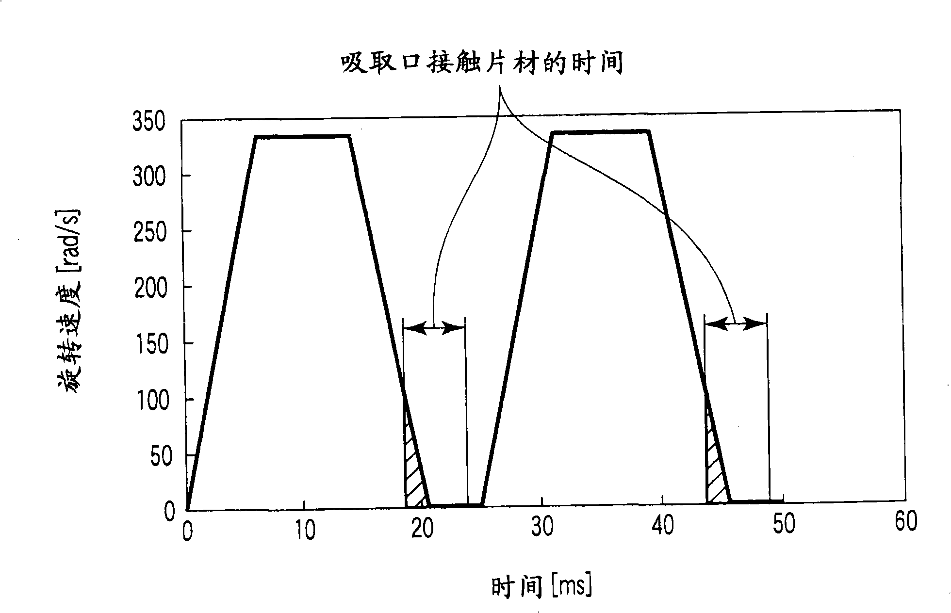
[0035] figure 1 A schematic plan view of a sheet take-out device 1 (hereinafter simply referred to as take-out device 1 ) according to a first embodiment of the present invention is shown. figure 2 is an enlarged view of the suction port 3 included in the take-out roller 2 in the take-out device 1 . image 3 is an example of a velocity diagram showing the velocity at which the take-out roller 2 rotates intermittently.

[0036] Such as figure 1 As shown, the take-out device 1 has: a loading section 12 on which a plurality of collected sheets P such as mail or slips to be processed are loaded in an upright position; a feeding mechanism (not shown) on which The feeding mechanism moves the loaded sheets P along the collecting direction ( figure 1 in the direction of the middle arrow F), and feed the first sheet P1 located at the front end of the ...


PUM


Abstract

A sheet takeout mechanism (10) has a takeout roller (2) that rotates in contact with a sheet located at a takeout position, and a motor (5) that intermittently rotates the takeout roller (2). A triangular suction port (3) is formed on a suction surface (2a) of the takeout roller (2) and has a vertex located downstream in a rotation direction (R) of the takeout roller (2). When a negative pressure is exerted on the sheet via the suction port (3), the suction force is weak at the beginning of suction and then increases gradually.

Description

technical field [0001] The present invention relates to a sheet take-out device that sucks and contacts a sheet placed at a take-out position, and then rotates to take out the sheet in a surface direction. Background technique [0002] Sheet material take-off devices are conventionally known which apply negative pressure to one of many sheets at the take-off position through a belt hole in an endless take-off belt to suck and contact the sheet , and then the take-out belt is intermittently advanced in the take-out direction to take out the sheet onto the conveyance path (for example, see Japanese Patent Application Laid-Open Publication No. 3735565). [0003] In addition to the extraction chamber, the device has a negative pressure chamber across the extraction belt opposite the extraction location and a chamber mask located between the negative pressure chamber and the extraction belt. Two masking holes are formed in the chamber mask, the two masking holes being separated ...

Claims


Application Information

Patent Timeline
Patent Type & Authority Applications(China)
IPC IPC(8): B65H3/10
CPCB65H3/10
Inventor 浅利幸生成冈良彦
Owner KK TOSHIBA
Why Eureka
Try Eureka