

Driving circuit and method for LCD device
A liquid crystal display device and drive circuit technology, applied in static indicators, nonlinear optics, instruments, etc., can solve the problems of high cost and complicated drive circuit wiring, and achieve the effect of simple wiring
- Summary
- Abstract
- Description
- Claims
- Application Information
AI Technical Summary
Problems solved by technology
Method used
Image

Examples
Embodiment Construction
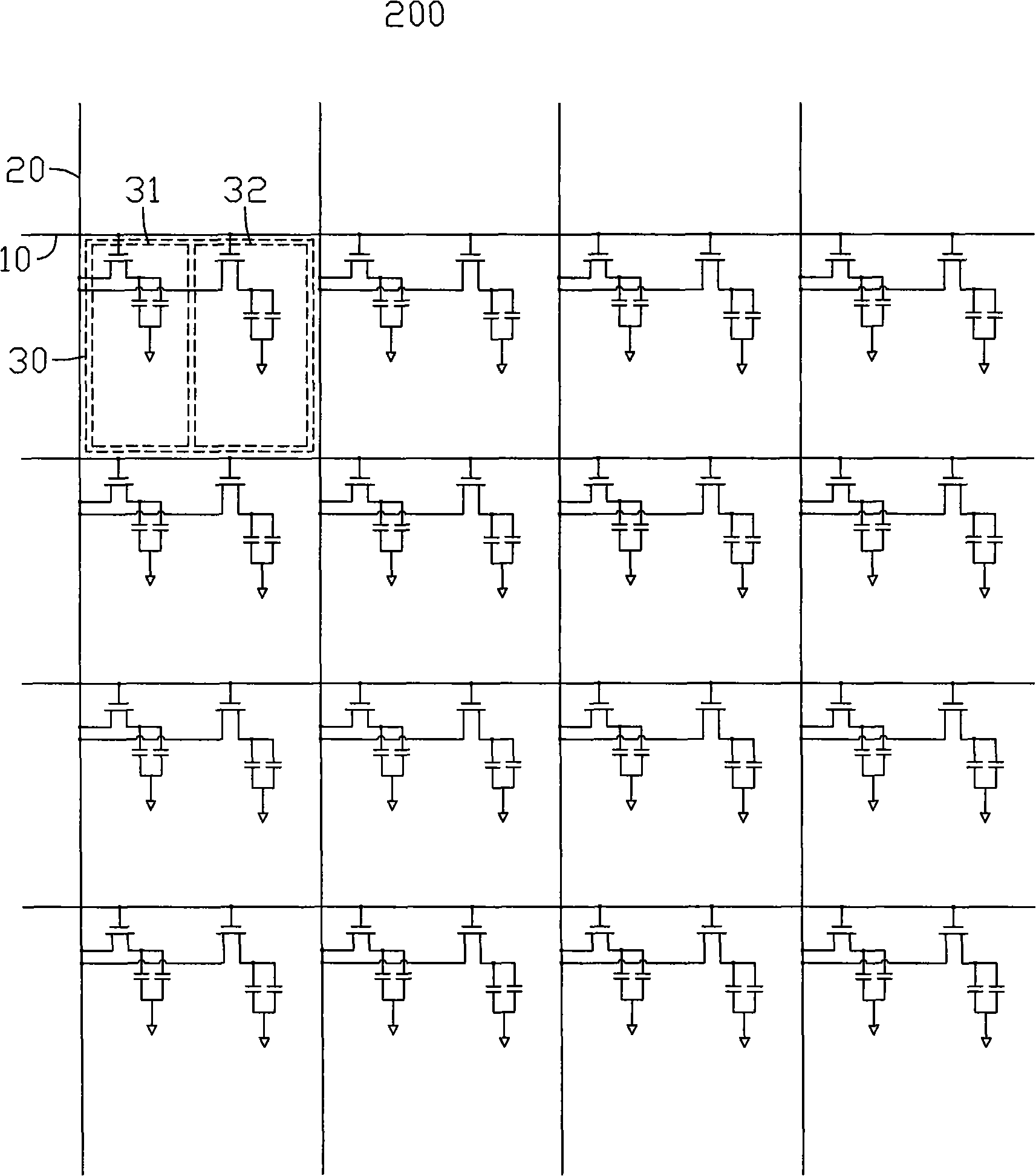
[0021] see image 3 with Figure 4 , image 3 It is a schematic diagram of the first embodiment of the driving circuit of the liquid crystal display device of the present invention, Figure 4 is a partially enlarged schematic diagram of the driving circuit of the liquid crystal display device shown in 3. The driving circuit 200 of the liquid crystal display device includes a plurality of scanning lines 10 , a plurality of data lines 20 and a plurality of pixel units 30 . The plurality of scan lines 10 intersect with the plurality of data lines 20 in isolation, and the smallest area formed by the intersection of the plurality of scan lines 10 and the plurality of data lines 20 defines the plurality of pixel units 30 . The liquid crystal display device is a multi-domain vertical alignment type liquid crystal display device.
[0022] The pixel unit 30 includes a first sub-pixel unit 31 and a second sub-pixel unit 32, the first sub-pixel unit 31 includes a first thin film tran...
PUM
 Abstract
Description
Claims
Application Information