Router with lighted base

A technology for routers and light sources, which is applied in the direction of routers, special forming/shaping machines, manufacturing tools, etc.

Inactive Publication Date: 2008-12-10
TECHTRONIC IND CO LTD
View PDF0 Cites 4 Cited by
  • Summary
  • Abstract
  • Description
  • Claims
  • Application Information

AI Technical Summary

Problems solved by technology

However, this structure still cannot always improve the situation, because other stru

Method used


Image

  • Router with lighted base
  • Router with lighted base
  • Router with lighted base

Examples


Embodiment Construction

[0018] The present invention is described below with reference to the drawings, in which like parts are indicated by like numerals. The relationship and function of the various components of the invention will be better understood from the following description. Each aspect so defined may be combined with any other aspect or aspects unless expressly stated to the contrary. Embodiments of the present invention are described below by way of example only, and the present invention is not limited to the embodiments shown in the drawings.

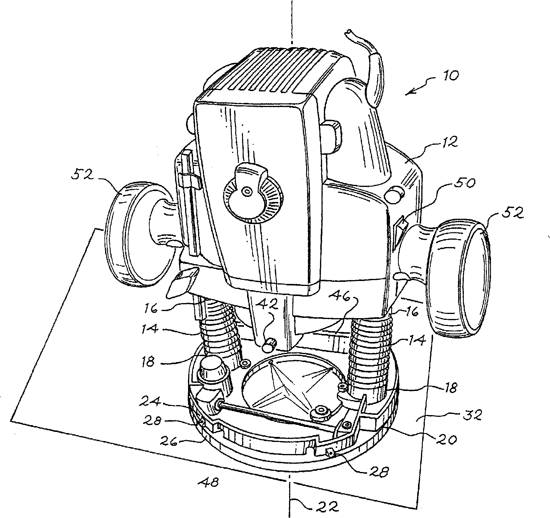
[0019] Refer to the accompanying drawings below and see figure 1 , which shows a hand-operated router 10 of the present invention. The hand-held router 10 includes a housing 12 and a handle 52 . At least one member 14 is disposed below the housing 12 . Member 14 has a first end 16 and a second end 18 . A first end 16 of at least one member 14 is connected to the housing 12 . The second end 18 of at least one member 14 is connected to the b...


PUM


Abstract

A hand operated router having a base, with a portion that is transparent. Disposed within the base is at least one light emitting source, where the light emitting source is designed to partially emit light towards a workpiece. The light emitting source may be battery operated or may receive power from the same source as the router.

Description

technical field [0001] The present invention relates to a power tool, and more particularly, to a router with an illuminated base. Background technique [0002] Routers are commonly used to cut workpieces. The design of a typical router sometimes casts shadows on the work and cut pieces and can block the user's view. This enables the user to either work in unsatisfactory lighting conditions or provide an additional light source to illuminate the workpiece and surrounding area. One way to provide additional light on the workpiece is to mount a lamp or lighting unit on the router housing. However, this configuration still does not always improve the situation, since other structures attached to the housing are located between the light source and the workpiece. Additionally, the focus and intensity of the light varies with the vertical position of the housing when attached to a plunger router. The present invention addresses these and other problems, as described below. ...

Claims


Application Information

Patent Timeline
IPC IPC(8): B23D7/02B23D9/00B23Q17/24B25F5/00B25F5/02
CPCB23Q17/2404B25H1/0092B27C5/10
Inventor 钟官伙张淦钧
Owner TECHTRONIC IND CO LTD
Why Eureka
Try Eureka