Humeral component of a shoulder joint prosthesis

A shoulder joint and component technology, which is applied in the field of humerus components, can solve the problem of unsuitable reversible shoulder prosthesis and the like

Active Publication Date: 2008-12-10
大卫·科林斯 +1
View PDF2 Cites 5 Cited by
  • Summary
  • Abstract
  • Description
  • Claims
  • Application Information

AI Technical Summary

Problems solved by technology

This of course does not apply to the use of inverted shoulder prostheses such as discussed above

Method used


Image

  • Humeral component of a shoulder joint prosthesis
  • Humeral component of a shoulder joint prosthesis
  • Humeral component of a shoulder joint prosthesis

Examples


Embodiment Construction

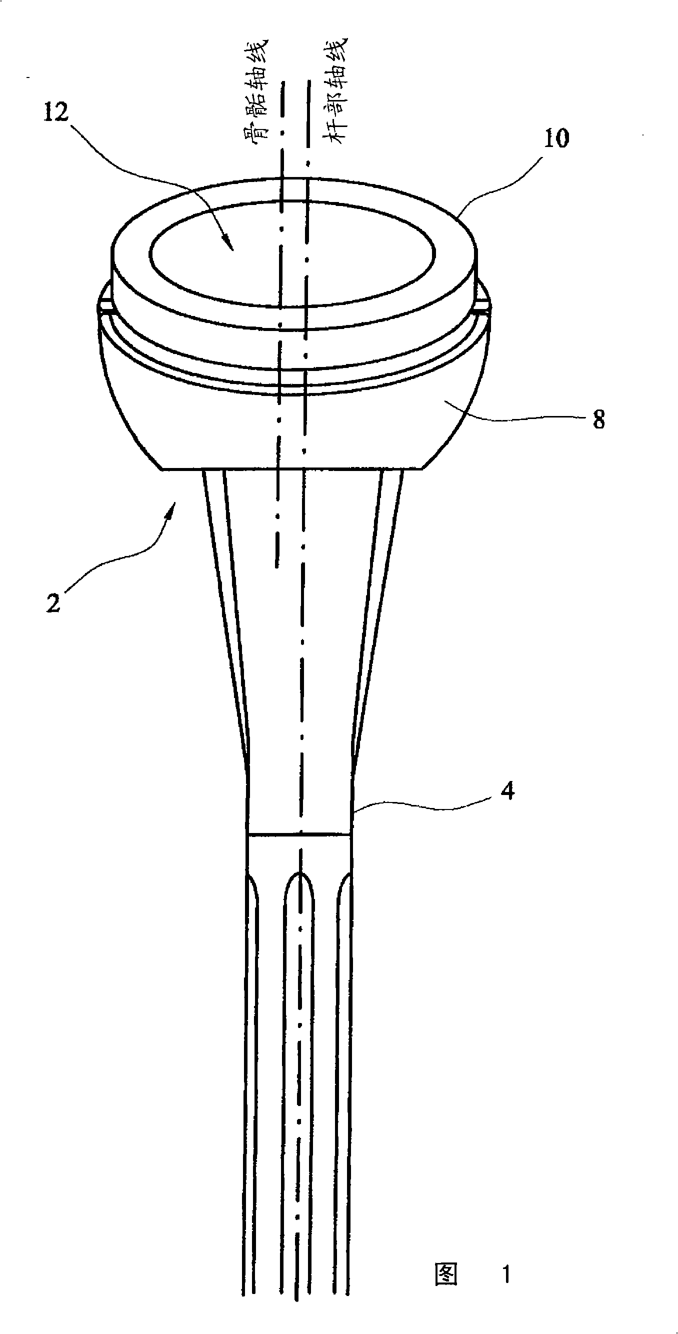
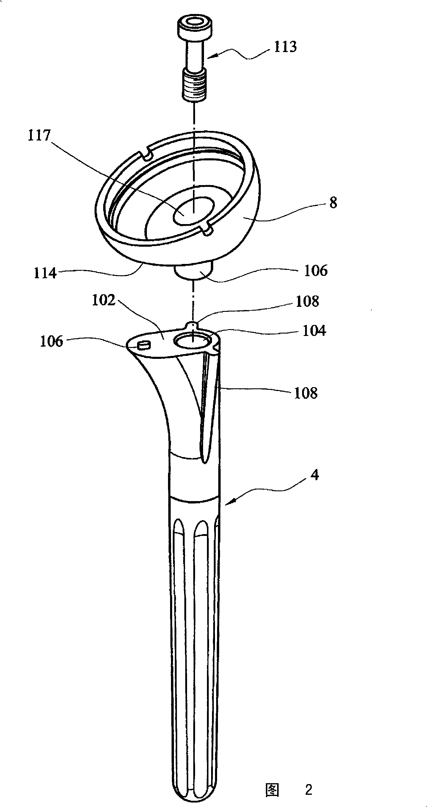
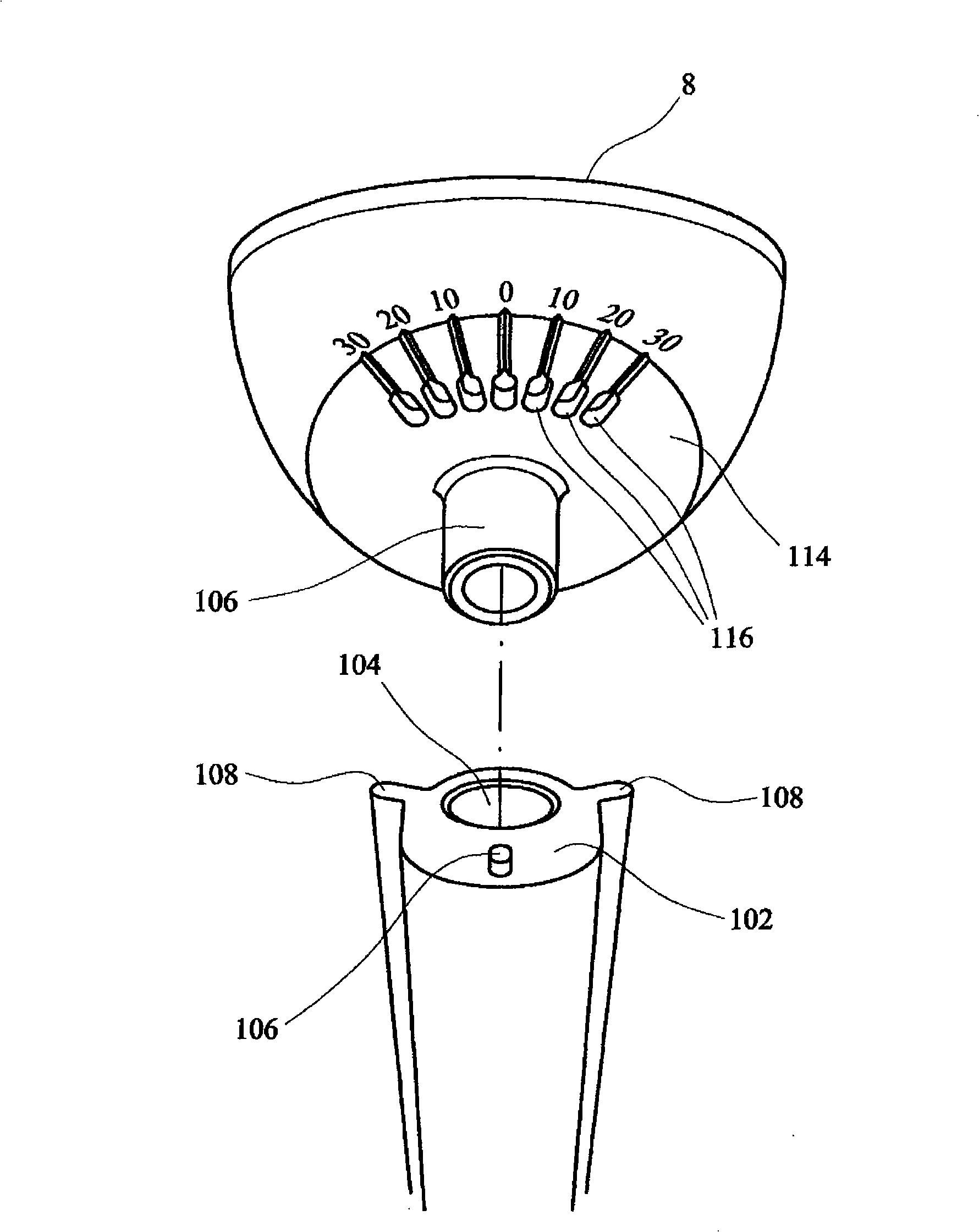
[0033]See attached drawings, Figures 1 through Image 6 The humeral component 2 in a reverse shoulder prosthesis is shown. The humeral component includes an elongated shaft section 4 for placement within the intramedullary cavity of a humerus 6 . The epiphyseal section 8 defines a recess for the bearing section 10 . The bearing section has a concave bearing surface 12 for articulation with a convex bearing surface of a glenoid component (not shown).

[0034] The shaft section 4, the epiphyseal section 8 and the load bearing section 10 are provided as separate modular sections which are assembled together prior to implantation to form the humeral component. Features included in modular orthopedic joint prostheses, especially shoulder prostheses, are already available, for example, from the DELTA and GLOBAL prostheses manufactured and sold by DePuy Products Inc and from the AEQUALIS prosthesis manufactured and sold by Tornier S.A. It is known that said features are suitable f...


PUM


Abstract

A humeral component of a reverse shoulder prosthesis (2) comprises an elongate stem part (4) for location within the intramedullary cavity of the humerus, and an epiphyseal part having a concave bearing surface (12) for articulation with the convex bearing surface (12) of a glenoid component (8). The elongate stem part (4) defines a stem axis and the concave bearing surface of the epiphyseal part defines an epiphyseal axis. The epiphyseal axis is offset posteriorly relative to the stem axis.

Description

technical field [0001] The present invention relates to a humeral component in a reverse shoulder prosthesis. Background technique [0002] A shoulder prosthesis includes a humeral component having a shaft section that can fit within the intramedullary cavity of the humerus, and a glenoid section. In a natural joint, the humeral component provides a convex head that is articulated on a concave bearing surface on the glenoid socket. This structure is reproduced in so-called "anatomical" shoulder prostheses, in which the humeral component includes a stem section and a head section with a convex load-bearing surface, and the glenoid component provides a concave into the bearing surface. The shaft segment is implanted within the humerus. The head section is fitted onto the shaft section (typically using a spigot and socket arrangement) such that the head section rests above the resection plane of the humerus. Anatomical prostheses are suitable for use in patients in which th...

Claims


Application Information

Patent Timeline
Patent Type & Authority Applications(China)
IPC IPC(8): A61F2/40A61F2/00A61F2/02A61F2/30
CPCA61F2/4014A61F2/4059A61F2002/30253A61F2002/30331A61F2002/30487A61F2002/305A61F2002/30507A61F2002/30538A61F2002/3054A61F2002/30604A61F2002/30616A61F2002/30617A61F2002/3082A61F2002/30884A61F2002/4022A61F2002/4037A61F2002/4044A61F2002/4051A61F2220/0025A61F2220/0033A61F2230/0076A61F2250/0006A61F2250/0097A61F2310/00011A61F2/40
Inventor 塞西尔·尼罗特迪戴尔·卡彭路德维希·泽鲍尔安德斯·埃克隆德利文·德维尔德迈克尔·沃思大卫·科林斯劳伦特·拉福斯D·庞塞特
Owner 大卫·科林斯
Why Eureka
Try Eureka