
Reel unit for spinning reel

A fishing reel, spinning-wheel-type technology, applied in the main field of the fishing reel of the spinning-wheel-type fishing reel

Active Publication Date: 2008-12-17
SHIMANO INC
View PDF3 Cites 11 Cited by
  • Summary
  • Abstract
  • Description
  • Claims
  • Application Information

AI Technical Summary

Problems solved by technology

However, when the moving part rises on the slope, the stress is concentrated on the fixed part, and a larger space is required on the fixed part to maintain the strength of the fixed part

Method used


Image

  • Reel unit for spinning reel
  • Reel unit for spinning reel
  • Reel unit for spinning reel

Examples


Embodiment Construction

[0038]

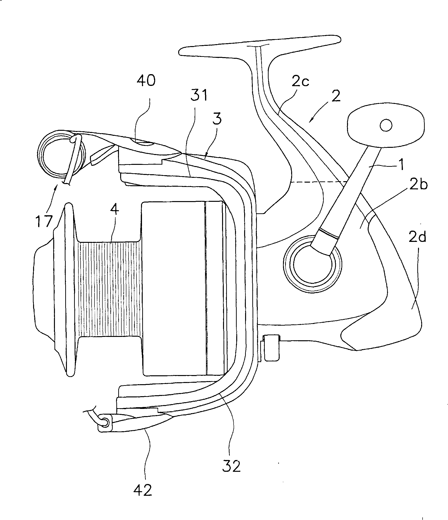
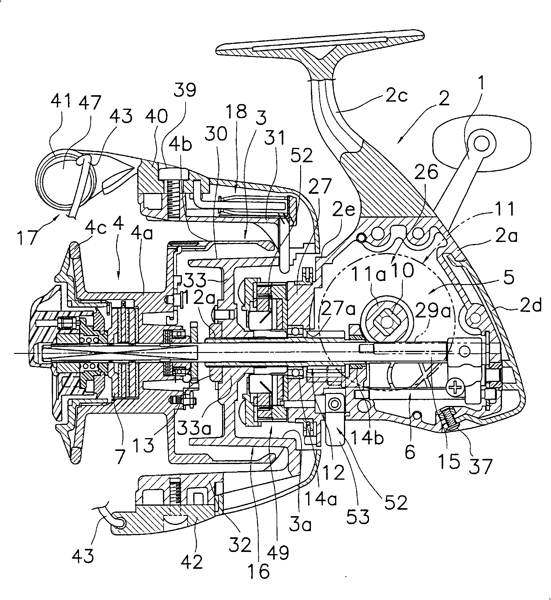
[0039] Such as figure 1 with figure 2 As shown, the spinning fishing reel adopting the first embodiment of the present invention has: fishing reel main body 2, rotor 3, spool 4, spool shaft 15, rotor driving mechanism 5, swing mechanism 6 and force unloading mechanism 7. Wherein, the fishing reel main body 2 is installed on the fishing rod, and supports the handle 1 which is rotatable relative to it. The rotor 3 has a fishing line guide arm 17 and is attached to the front portion of the fishing reel body 2 so as to be rotatable about an axis in the front-rear direction. The fishing line guided by the rotor 3 is wound around the outer peripheral surface of the spool 4 , and the spool 4 is disposed in front of the rotor 3 so as to be movable back and forth. The spool shaft 15 is attached to the reel main body 2 so as to be movable in the front-rear axial direction, and the spool 4 is attached to the tip end via the unloading mechanism 7 . The rotor drive mechanism...


PUM


Abstract

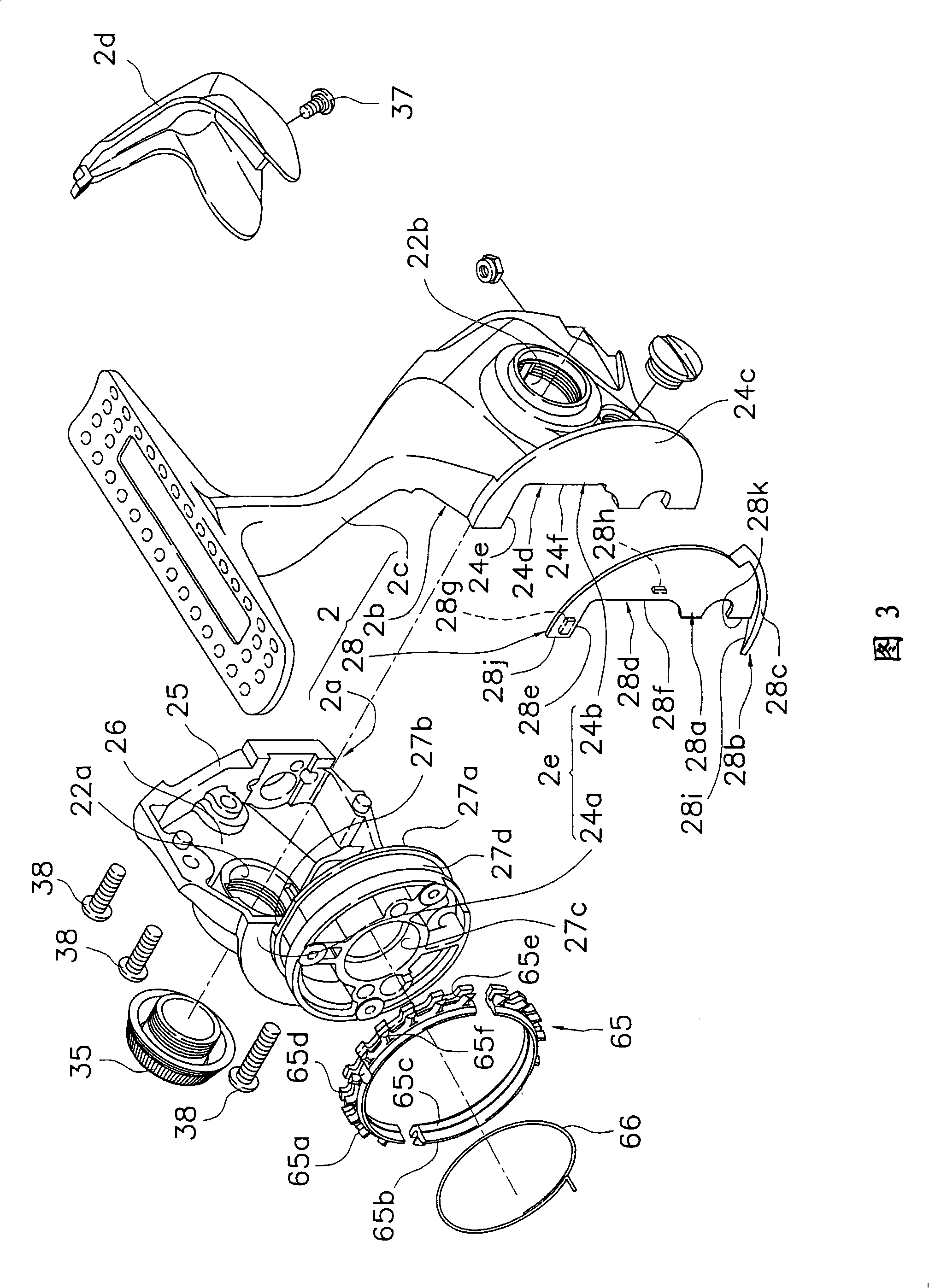
A reel unit for a spinning reel includes a housing unit, a lid portion, and a returning member. The housing unit includes a cylindrical portion and a somewhat semicircular first flange portion arranged behind the cylindrical portion. The lid portion has a somewhat semicircular second flange portion arranged behind and forming a gap with the rear surface of the cylindrical portion. The lid portion is detachably coupled to the housing unit. The returning member is detachably mounted in gap and includes a plate-like arranging portion disposed in gap and a protrusion gradually protruding from a front side of the arranging portion to face the first flange portion. The protrusion 28b has a first sloped surface contactable with a bail tripping mechanism.

Description

technical field [0001] The present invention relates to a fishing reel main body, in particular to a fishing reel main body of a spinning fishing reel, on which a rotor rotatable relative to it is supported and a rotor capable of moving back and forth relative to it is supported. spool, the rotor has a guide arm turning mechanism, which makes the fishing line guide arm swingable between the fishing line winding position (line take-up position) and the fishing line setting position return to the fishing line from the fishing line setting position Winding gesture. Background technique [0002] The spinning fishing reel has a fishing reel main body, a reel for winding the line, and a rotor, wherein the fishing reel main body has a fishing rod mounting seat portion that can be mounted on a fishing rod; It is installed on it in a way to move back and forth; the rotor is rotatably installed on the main body of the fishing reel for winding the fishing line on the reel. The main b...

Claims


Application Information

Patent Timeline
Patent Type & Authority Applications(China)
IPC IPC(8): A01K89/00
CPCA01K89/027A01K89/0117A01K89/0114A01K89/01083A01K89/011221A01K89/0108A01K89/01
Inventor 平冈宏一菅原谦一
Owner SHIMANO INC
Learn More