Tape cassette and tape printing system

A printing system and tape cassette technology, applied in printing devices, printing, typewriters, etc., can solve the problems of increased printing tape volume, larger tape cassette size, and soaring operating costs, so as to reduce operating costs and prevent erroneous transportation. Effect

Inactive Publication Date: 2008-12-17
BROTHER KOGYO KK
View PDF2 Cites 7 Cited by
  • Summary
  • Abstract
  • Description
  • Claims
  • Application Information

AI Technical Summary

Problems solved by technology

[0006] However, since the adhesive tape needs to be pasted to the printing surface of the film tape after characters etc. have been printed on the film tape, the adhesive tape reel and the pasting roller on which the adhesive tape is wound must be accommodated in the In a cassette in a conventional tape printing device
[0007] As a result, the size of the tape cassette becomes large, thereby producing a problem that the overall size of the printing apparatus must inevitably become large in order to be able to mount the cassette mounting unit.
As a result, the front side blank portion of the generated printing tape (the blank portion corresponding to the distance between the cutting position of the printing tape and the thermal print head of the tape printing device) becomes large, thereby causing a problem that consumed Ribbon volumes increased, which caused running costs to skyrocket
[0011] Also, the tape output from the tape printing device with unprotected adhesive cannot be easily stored for a long time without being bonded to the target body

Method used


Image

  • Tape cassette and tape printing system
  • Tape cassette and tape printing system
  • Tape cassette and tape printing system

Examples


no. 1 example

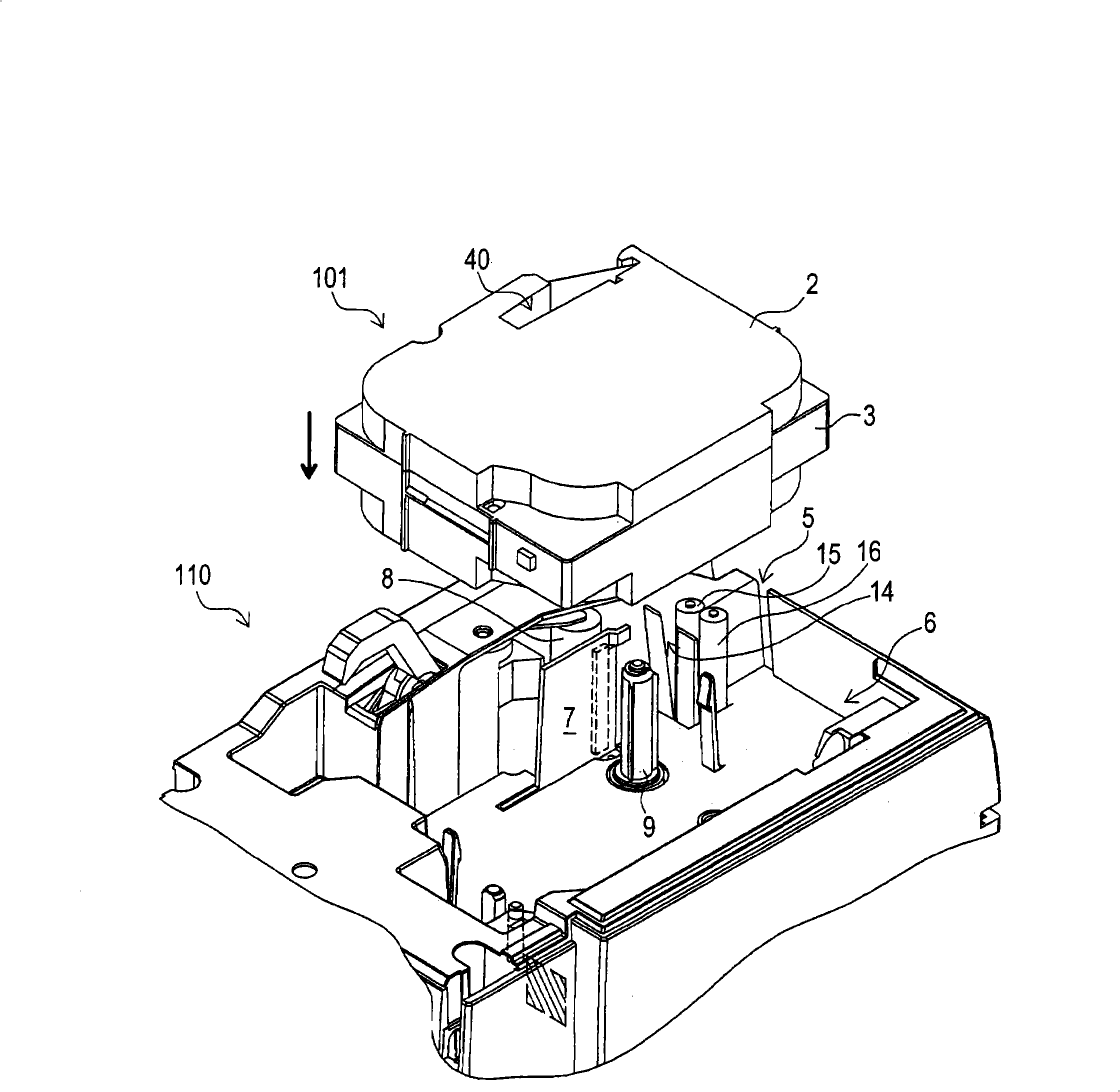
[0069] will now be based on figure 1 A description will be given of the tape cassette and the tape printing apparatus according to the first embodiment with reference to FIG. 2 . Here, the tape printing device includes a tape conveying device.

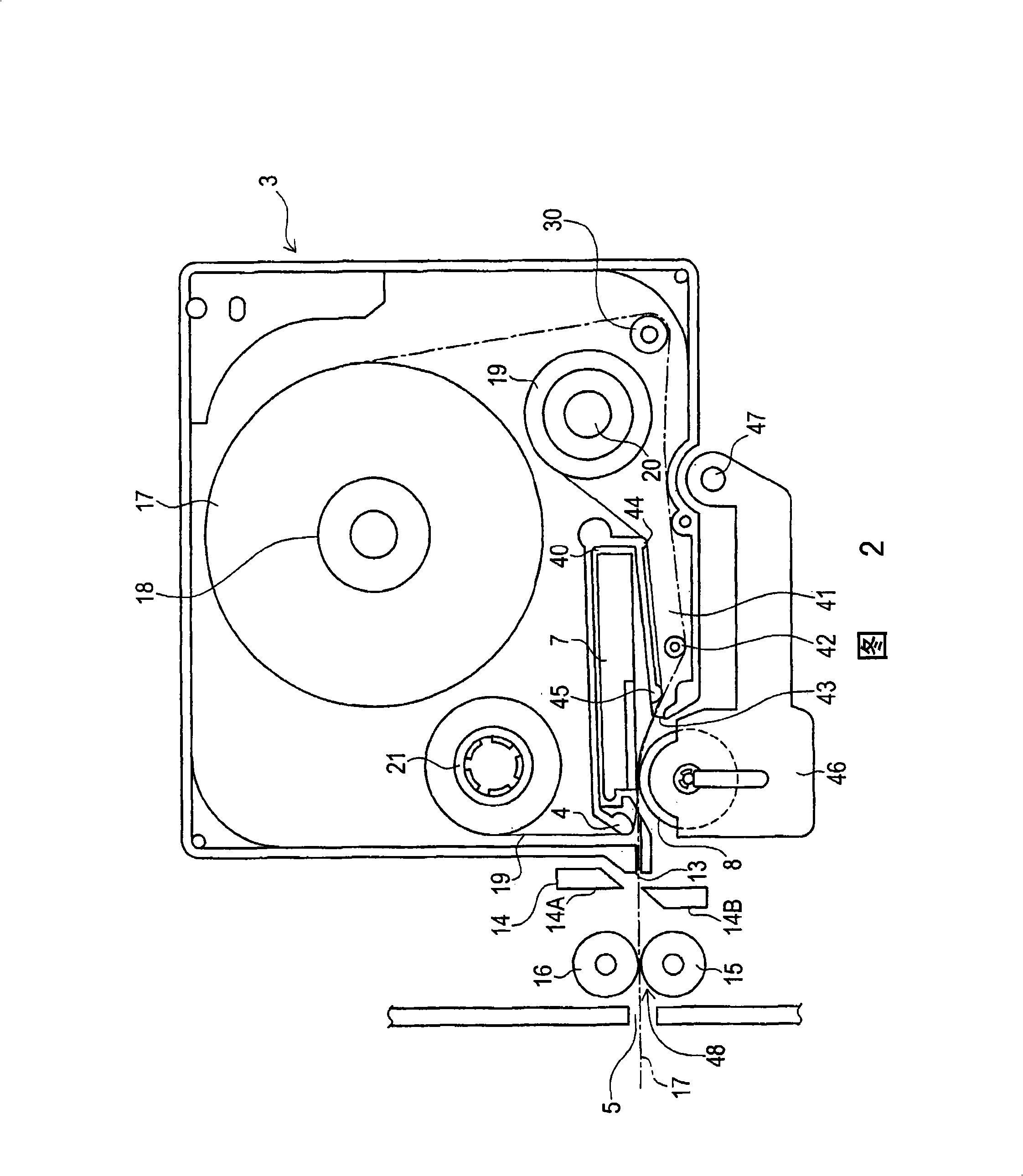
[0070] exist figure 1 In this case, the tape cassette 101 is detachably mounted on the cassette mounting portion 6 provided in the tape printing apparatus 110 . The tape cassette 101 has an upper case 2 and a lower case 3 . The upper case 2 serves as a cover member for covering the upper surface of the lower case 3 . The lower case 3 has a film tape reel 18 on which a film tape 17 is wound, and the film tape reel 18 is provided at a position slightly above a central portion thereof. The lower case 3 also has an ink ribbon reel 20 and an ink ribbon take-up reel 21 arranged at the lower right position of the film tape reel 18, the ink ribbon 19 is wound on the ink ribbon reel 20, and the ink ribbon take-up reel 21 takes the ink rib...

no. 2 example

[0099] Next, based on Figure 5 and 6 to describe the tape cassette and the tape printing apparatus according to the second embodiment. The configuration of the tape cassette 101 according to the second embodiment is the same as that of the tape cassette 101 according to the first embodiment. Also, the configuration of the tape printing apparatus 210 according to the second embodiment is basically the same as that of the tape printing apparatus 110 according to the first embodiment. In the following description, the same elements as those of the tape cassette 101 and the tape printing apparatus 110 according to the first embodiment are denoted by the same reference numerals.

[0100] In the tape printing device 110 according to the first embodiment, the tape conveying roller 16 is provided in the tape printing device 110 . However, in the second embodiment, the tape feed roller 77 has the same function as the tape feed roller 16 in the first embodiment, and the tape feed rol...

no. 3 example

[0123] In the above-mentioned second embodiment, when the film tape is conveyed after printing, the auxiliary paper medium is rewound on the auxiliary paper medium take-up reel. As a result, it is no longer necessary to peel off the secondary paper medium when adhering the printed film tape to the target body. However, the adhesive layer of the film tape is not protected at this time. This makes it difficult to store a film strip formed in the above manner for a long period of time when the film strip is not bonded to the target body.

[0124] The third embodiment to be described is made to solve these problems. will then be based on Figure 9 A tape cassette, sub-cassette, and tape printing apparatus according to a third embodiment will be described with FIG. 10 .

[0125] The configuration of the tape cassette 101 according to the third embodiment is the same as that of the tape cassette 101 according to the second embodiment.

[0126] Also, the configuration of the tape...


PUM

PropertyMeasurementUnit
Melting pointaaaaaaaaaa

Abstract

A tape cassette includes an ink ribbon provided with a base film coated with an ink layer thereon and a film tape provided with a transparent film with an adhesive layer formed on one surface thereof. When an adhesive layer of the film tape and the ink layer of the ink ribbon of the tape cassette come into contact at a print position, the ink layer is adhered onto the adhesive layer on condition that the adhesive layer is heated to exhibit self-adhesive properties, and characters and the like are printed on the film tape. Also, an auxiliary sheet medium comes into contact with the adhesive layer. Further, a conveying roller does not come into contact with the adhesive layer.

Description

[0001] Cross References to Related Applications [0002] This application is based on and claims priority from Japanese Patent Application No. 2007-154413 filed on June 11, 2007 and Japanese Patent Application No. 2007-337422 filed on December 27, 2007, which are hereby incorporated by reference The full text of these patent applications. technical field [0003] One or more aspects of the present invention relate to a tape cassette used in a printing mechanism using an ink ribbon having an ink layer formed on one surface thereof, and a transparent ink ribbon having an adhesive layer formed on one surface thereof. A film-formed printing tape, and also relates to a tape printing device using the above-mentioned tape. Also, one or more aspects of the present invention relate to a printing system including the tape cassette and the tape printing device. Background technique [0004] Various types of tape printing devices have conventionally been proposed for producing tapes ...

Claims


Application Information

Patent Timeline
IPC IPC(8): B41J3/407B41J2/325B41J15/04B41J33/02B41J33/14
Inventor 山口晃志郎
Owner BROTHER KOGYO KK
Why Eureka
Try Eureka