
Ventilated wind pipe

A blower and a part of the technology, applied in the field of ventilation equipment, can solve the problems of time-consuming, laborious, difficult to operate, difficult to operate, etc., and achieve the effect of reducing manufacturing costs, tight joints, and not easy to leak air

Inactive Publication Date: 2008-12-17
宋银忠
View PDF0 Cites 4 Cited by
  • Summary
  • Abstract
  • Description
  • Claims
  • Application Information

AI Technical Summary

Problems solved by technology

The above-mentioned double-reversed-side blower docking method, when dealing with air leakage, needs to open the double-reverse side, and then turn the side back after processing, which is not easy to operate; when the fan needs to be replaced, not only the double-reverse side needs to be opened, but also It is time-consuming and labor-intensive to remove the two steel rings with the same diameter that are nested together, and then replace the steel rings and double-sided sides. It is more difficult to operate without stopping the fan.
If the fan is stopped, the personnel should be evacuated to suspend production. In actual production, workers often operate in violation of regulations and stop the fan without evacuating the personnel to replace the air duct or deal with air leakage. The gas concentration in the mine exceeds the limit. It is easy to cause production accidents and there are potential safety hazards

Method used


Image

  • Ventilated wind pipe
  • Ventilated wind pipe
  • Ventilated wind pipe

Examples


Embodiment Construction

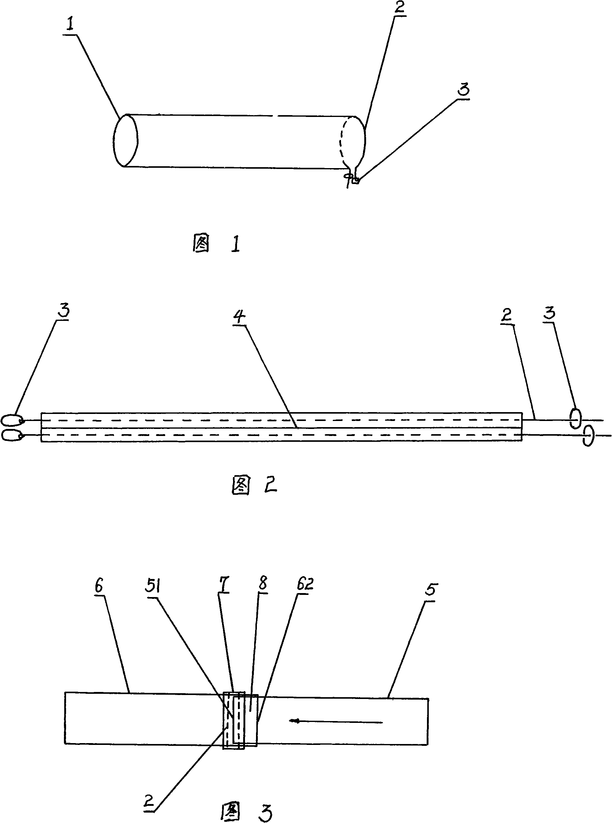
[0013] As shown in FIG. 1 , one end of the blower has a steel ring 1 , the other end is threaded with a rope 2 , and both ends of the rope 2 have locks 3 . As shown in Figure 2, there are two ropes 2 in the tight band. In order to prevent the ropes from being entangled with each other, the two ropes are separated. It can be isolated by two ropes, or other isolation methods can be used. As shown in Figure 3, the schematic diagram of the butt joint structure of the air duct, the arrow points to the air flow direction, 5 indicates the upper section of the air duct, 6 indicates the lower section of the air duct, and 7 indicates the tight band. The operation steps to connect the air cylinder are: 1. Put the rope end 62 of the lower air cylinder 6 over the steel ring end 51 of the upper air cylinder 5, tighten the rope of the rope end 62 of the air cylinder 6, and buckle the rope lock Buckle, but not too tight, so that the air duct is not blown open. Two, adjust air cylinder 6, ma...


PUM


Abstract

The invention discloses a ventilatorduct, one end of each section of the ventilatorduct is provided with a steel ring, and the other end thereof is provided with a rope, the end provided with the rope of the next section of the ventilatorduct is sheathed at the end provided with the steel ring of the previous section of the ventilatorduct with an overlapped part; the overlapped part is tied with a tightening strap, the tightening strap is pressed on the steel ring, two ropes of the tightening strap are respectively positioned at two sides of the steel ring; after the two ropes are strained and locked, two sections of the ventilatorducts are butt-jointed together tightly by the tightening strap, the joint is tight and not easy to leak air, and firm and reliable. The ventilatorduct of the invention is not provided with a double-reverse edge structure, is simple, fast, and labor-saving when replacing the wind cone, the replacement can be completed quickly without stopping the air blower or affecting the wind supply of the tunneling working surface. The air leak caused by the distortion of the extruded steel ring of the ventilatorduct can be handled simply without much effort due to no double-reverse edge structure. Each section of the ventilatorduct of the invention is only provided with one steel ring, thus reducing the manufacturing cost.

Description

Technical field: [0001] The invention relates to underground or tunnel ventilation equipment, in particular to a ventilation air cylinder. Background technique: [0002] In underground excavation production or tunnel construction, it is necessary to send air to the underground or tunnel through the air duct, and the multi-section air duct forms an air duct through butt joints to send fresh air into the bottom of the well. The butt connection of each section of the air duct should be tight, and the operation of replacing the air duct or dealing with air leakage should be simple and easy. The air duct in the prior art has a steel ring at both ends of each section, and has a hemming part. Fold the edge back, and then fold back the two overlapping edges at the same time. With the extension of the air cylinder, the pressure inside the air cylinder close to the fan is increasing, and air leakage often occurs at the joint of the two air cylinders, and even the air cylinder is blo...

Claims


Application Information

Patent Timeline
Patent Type & Authority Applications(China)
IPC IPC(8): E21F1/04
Inventor 宋银忠
Owner 宋银忠
Learn More