Yarn clamping device for underwinding yarns on spindles of a ring spinning or ring twisting machine
A technology of ring spinning machine and clamping device, which is applied in the direction of spinning machine, continuous winding spinning machine, textile and paper making, etc. It can solve the problems of unsatisfactory and satisfactory safety, and achieve The effect of reliable removal
Inactive Publication Date: 2010-12-01
京特·柯尼希
View PDF8 Cites 0 Cited by
- Summary
- Abstract
- Description
- Claims
- Application Information
AI Technical Summary
Problems solved by technology
This design is unsatisfactory because the yarn wound on the bottom of the tube can only be inserted into the wedge-shaped clamping slit that closes at low speed
Moreover, the exact control of the delivery speed at this stage does not allow for satisfactory safety during clamping during bobbin change
Method used
View moreImage
Smart ImageViewing Examples

Examples
Embodiment Construction
Login to view more PUM
 Abstract
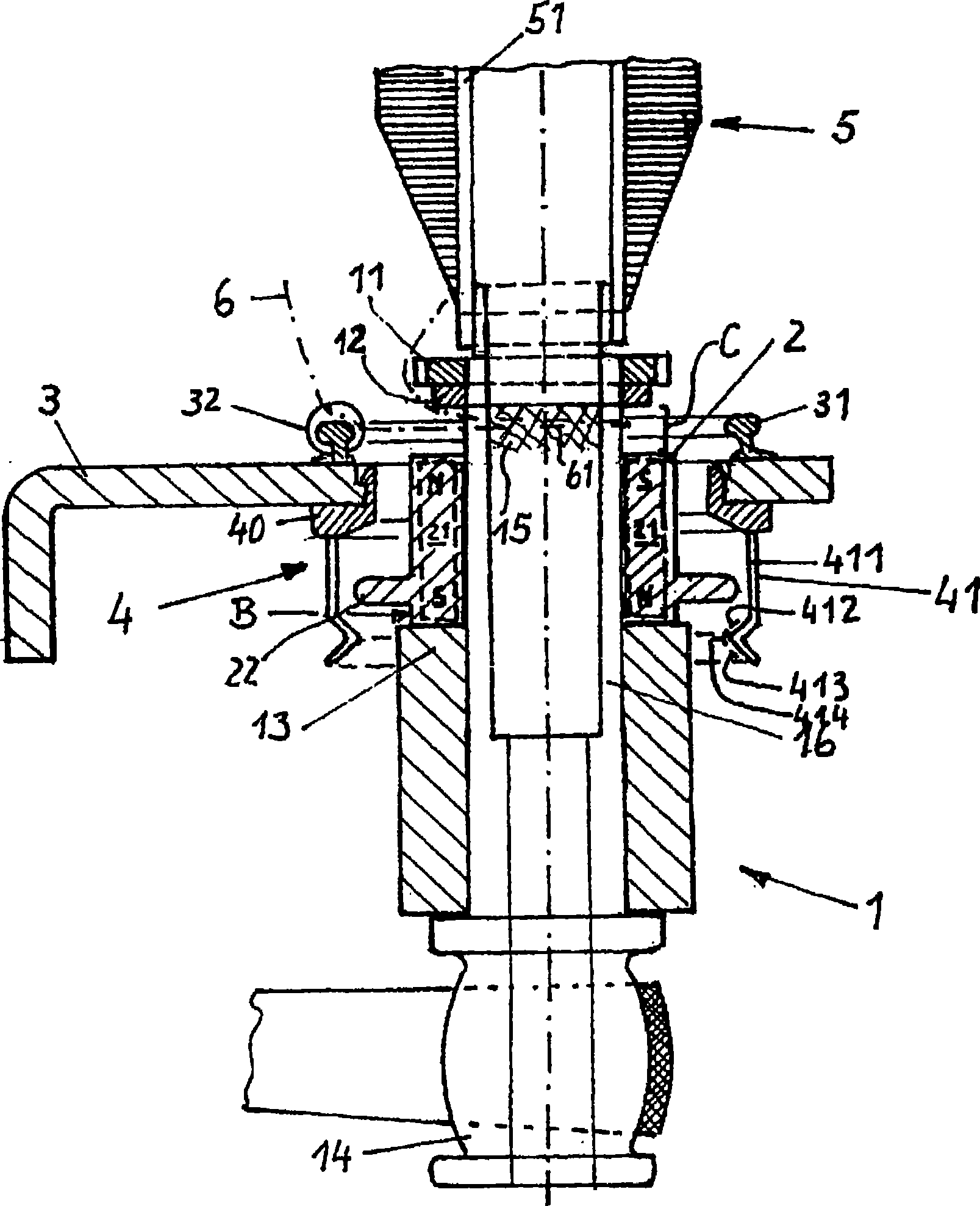
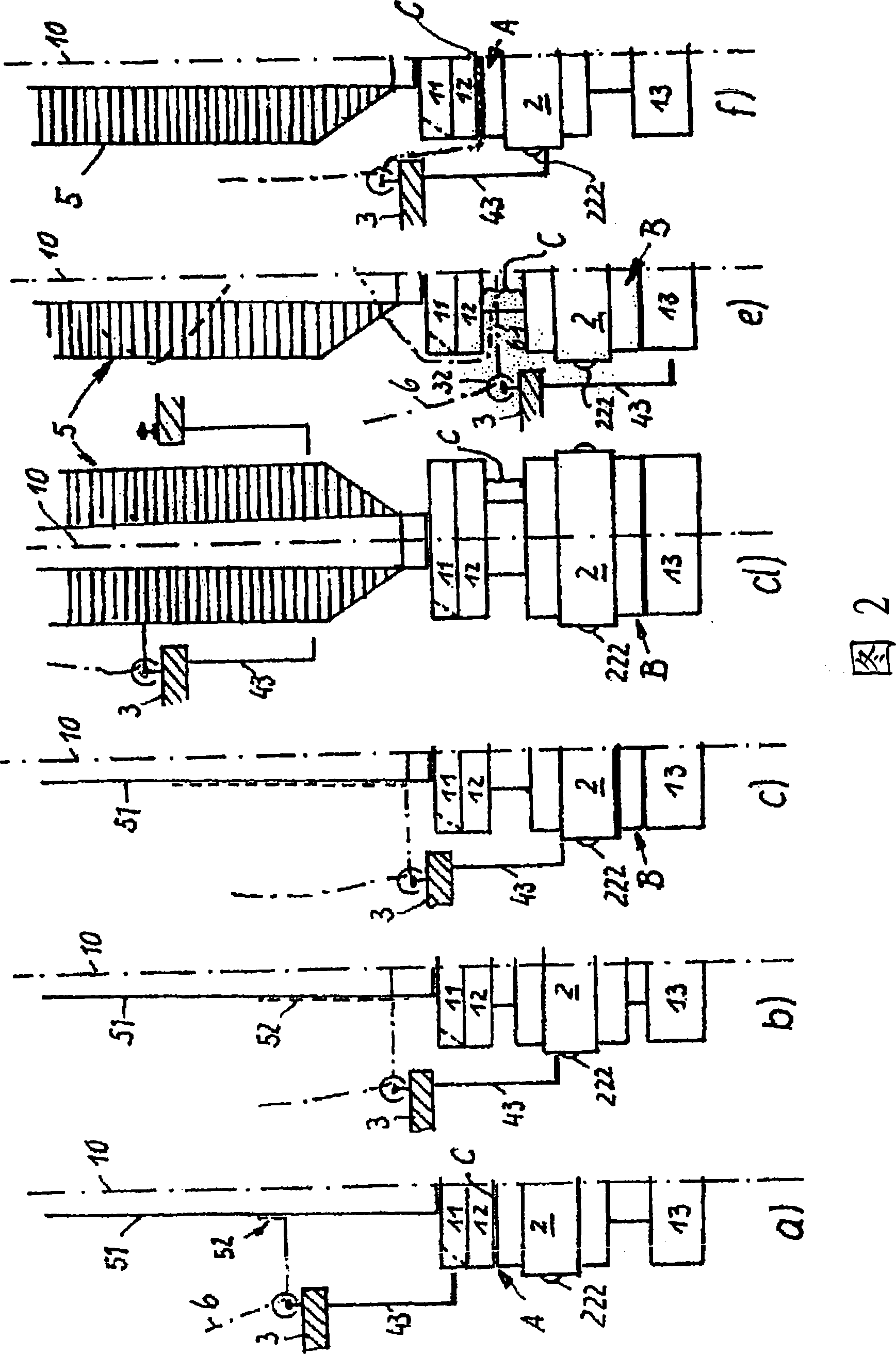
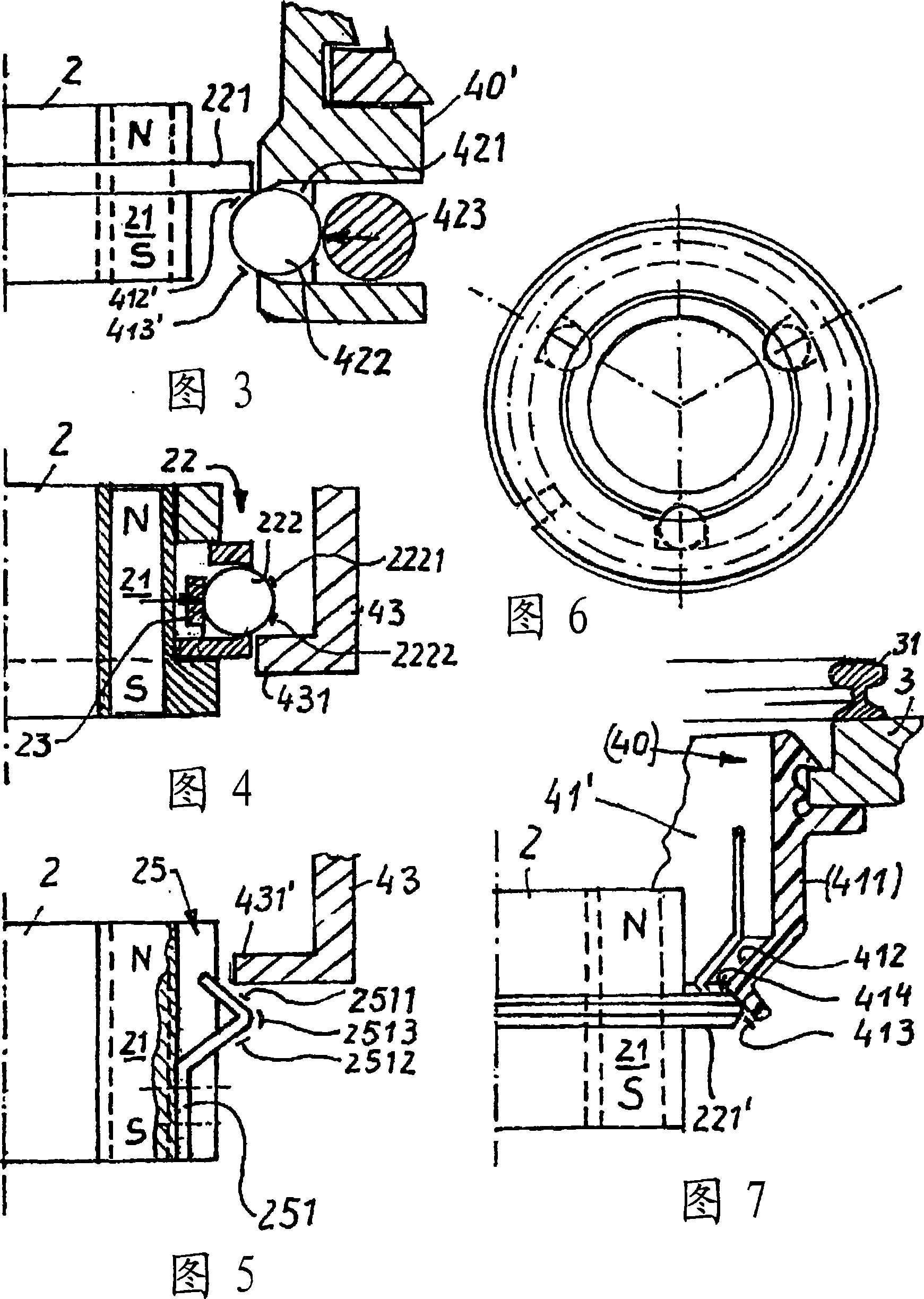
The invention relates to a thread clamping device for lower winding threads on spindles (1) of a ring spinning frame or ring twisting frame. A clamping sleeve (2) is provided between a clamping ring (12) and a radially protruding flange (13) on the spindle which can be axially displaced between a clamping position (A), which is defined by the position on the clamping ring (12), and an open position (B). The clamping sleeve (2) is associated with an actuation device (4) for the axial displacement thereof, which co-operates with radially extending means on the clamping sleeve (2). The clamping sleeves (2) are associated with elements (21; 17) for fixing the position thereof at least in the clamping position (A). The aim of the invention is to introduce lower windings into the clamping gap and to improve the removal thereof from the clamping gap.; As a result, the actuation elements (41) and / or the radially protruding means (22) are maintained on the clamping sleeve (2) in a radially, elastically touching manner in relation to each spindle axis (10) and are provided (C) with rising sloping surfaces (412, 413) which are radially effective in both relative directions of movement.
Description
Yarn clamping device for underwinding yarn on the spindles of ring spinning machines or ring twisting machines technical field The invention relates to a yarn clamping device for underwinding a yarn on a spindle of a ring spinning machine or a ring twisting machine, wherein an underwinding crown is arranged on the spindle a clamping ring and a radially projecting collar at a distance below the clamping ring; wherein on the spindle an axially movable clamping sleeve is positioned between the clamping ring and the collar; Wherein the clamping sleeve is movable by an actuating device between a clamping position defined by abutting against the clamping ring and an open position defined by abutting against the collar to open or close a clamp and wherein the clamping sleeve is equipped with: radially extending parts for operating a plurality of actuating elements of the actuating device; and for fixing the position of the clamping sleeve in at least the closed position multiple el...
Claims
Login to view more Application Information
Patent Timeline
 Patent Type & Authority Patents(China)
IPC IPC(8): D01H1/38
CPCD01H1/38
Inventor 京特·柯尼希
Owner 京特·柯尼希
- R&D Engineer
- R&D Manager
- IP Professional
Why Eureka
- Industry Leading Data Capabilities
- Powerful AI technology
- Patent DNA Extraction
Try Eureka
Browse by: Latest US Patents, China's latest patents, Technical Efficacy Thesaurus, Application Domain, Technology Topic.
© 2024 PatSnap. All rights reserved.Legal|Privacy policy|Modern Slavery Act Transparency Statement|Sitemap