Screw structure

A technology of structure and screw, which is applied in the field of screw structure, and can solve problems such as the skew of the rod body 1, damage to the screw quality, and increased resistance of the threaded part 2, etc.

Inactive Publication Date: 2008-12-24
EASYLINK IND
View PDF0 Cites 1 Cited by
  • Summary
  • Abstract
  • Description
  • Claims
  • Application Information

AI Technical Summary

Problems solved by technology

[0004] Generally speaking, the above-mentioned existing screw structure has the following disadvantages, because the tapping angle formed by the threaded part 2 is too large, and the circular arc peripheral edge of the threaded part 2 is used for cutting and tapping work, so that the threaded part 2 is in the process of When the contact area with the object is too large during cutting, the resistance encountered by the threaded part 2 during the screwing process will also increase relatively. Therefore, screwing the existing screw structure into the object requires a large amount of rotational torque and work. Over time, it is easy to cause the rod body 1 to be skewed or the screwed object to be damaged due to excessive force, thereby destroying the screwing quality

Method used


Image

  • Screw structure
  • Screw structure
  • Screw structure

Examples


Embodiment Construction

[0021] In order to make the above-mentioned and other objects, features and advantages of the present invention more obvious and easy to understand, the preferred embodiments of the present invention, together with the accompanying formula, are described in detail as follows:

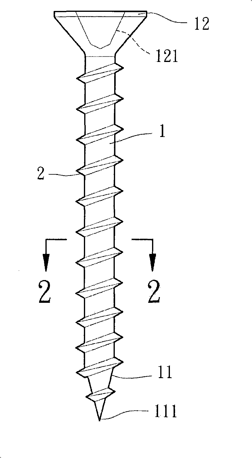
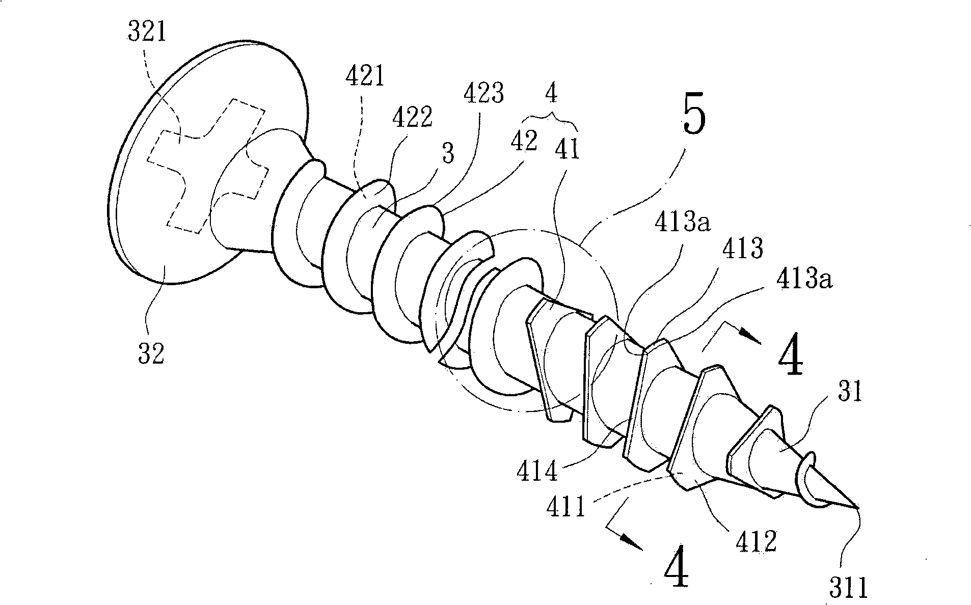
[0022] Please refer to image 3 , 4 As shown, the screw structure of the preferred embodiment of the present invention includes a rod body 3 and a threaded portion 4 , the rod body 3 is in the shape of a round rod, one end of the rod body 3 forms a tapered surface 31 , and the other end is provided with a head 32 . The tapered surface 31 has a tip 311 located at the end of the tapered surface 31 , which abuts against the surface of an object (not shown) to perform hole reaming action. The top of this head 32 offers a driving groove 321, and this driving groove 321 can be selected from the geometry structures such as inline, cross or regular polygon, and it can be used for inserting a tool (not shown, f...


PUM


Abstract

The invention relates to a screw structure, which comprises a pole body and a screw thread part; one end of the pole body is provided with a conical surface, and the other end of the pole body is provided with a head part. The screw thread part is formed on the peripheral surface of the pole body and provided with a first screw tooth part and a second screw tooth part. An overlooking shape of the first screw tooth part is a polygon structure; each corner of the first screw tooth part is respectively provided with a tapping part; and a flat and straight part is formed between the adjacent tapping parts. The second screw tooth is arranged between the head part of the pole body and the first screw tooth part. A sharp cutting angle is formed by the tapping part, thereby reducing a resistance occurring when an object is screwed in and improving a screwing efficiency.

Description

technical field [0001] The present invention relates to a screw, in particular to a screw with two thread portions with different tapping angles formed on a shank, wherein one of the thread portions is selected as a polygonal structure so that the shank can be easily screwed into an object. structure. Background technique [0002] Existing screw configurations such as figure 1 , 2 As shown, it includes a rod body 1 and a threaded portion 2 , the rod body 1 is in the shape of a round rod, and one end thereof is processed to form a tapered surface 11 . The other end of the rod body 1 has a head 12 . The tapered surface 11 has a tip 111 located at an end of the tapered surface 11 . A driving slot 121 is formed on the top of the head 12 , which can be inserted into a tool (not shown, such as a screwdriver, etc.), and the rod body 1 is driven to rotate by turning the tool. The threaded part 2 is arranged in a continuous helical ring on the outer peripheral surface of the rod...

Claims


Application Information

Patent Timeline
Patent Type & Authority Applications(China)
IPC IPC(8): F16B25/10
Inventor 曹天福
Owner EASYLINK IND
Why Eureka
Try Eureka