Valve

A valve shell and valve technology, applied in the field of valves, can solve the problems of affecting the activity of the spring tongue, the tendency of valve error is large, hindering serial mass production, etc., to achieve the effect of ensuring torque balance and simple suspension

Active Publication Date: 2008-12-24
FESTO AG & CO KG
View PDF4 Cites 2 Cited by
  • Summary
  • Abstract
  • Description
  • Claims
  • Application Information

AI Technical Summary

Problems solved by technology

Even under such preloaded conditions, it is still limited to a limited structural length of the reed, because the reed would otherwise have a severe arching phenomenon between the holding section and the loading section, which in turn requires Many spatial positions can even affect the mobil

Method used


Image

  • Valve
  • Valve
  • Valve

Examples


Embodiment Construction

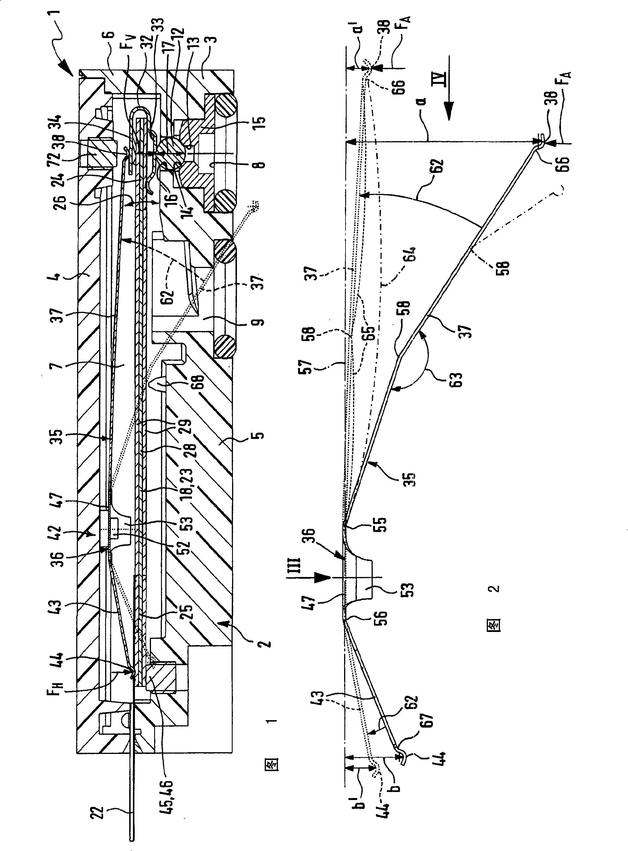
[0033] FIG. 1 shows a preferred embodiment of a valve 1 designed according to the invention as a piezoelectric valve. Of course, the invention is also suitable for valve types with other operating concepts.

[0034]FIG. 1 contains a valve housing 2 which is preferably composed of a valve housing body part 3 and a valve housing cover part 4 fixed thereon in a sealing manner. The valve housing body part 3 has a bottom wall 5 and a side wall 6 protruding from the bottom wall, the valve housing cover part 4 is arranged on the end region of the side wall 6, so that the valve housing cover part and the valve housing body part 3 jointly form a valve chamber 7. The valve housing cover 4 can be inserted at least partially into the valve housing body part 3 . Preferably, the valve housing cover part 4 is glued or welded to the valve housing body part 3 in a sealing manner.

[0035] The valve 1 of the present embodiment is designed as a 2 / 2-directional valve, although other functions ...


PUM


Abstract

The present invention relates to a valve with a valve member prestressed to an initial position through a bearing spring (35). The prestressing is generated by a reed (37) which is deflected to a prestressed working position from a neutral position without prestressing relative to a retaining segment (36) along a deflecting direction (62). The reed (37) is provided with at least one inflexion (58), so the reed is bended little although big deflection exists, and therefore only little installation space is required.

Description

technical field [0001] The invention relates to a valve with at least one valve housing and at least one valve element movable relative to the valve housing which can be prestressed into an initial position by means of at least one leaf spring, whereby the leaf spring There is at least one reed, which extends between a retaining section which is firmly fixed to the housing and a loading section which transmits the preload to the valve member, and is mounted in such a way that the preload is obtained. The reed is deflected from its untensioned neutral position into a prestressed working position in the direction of deflection due to the support by the valve element. Background technique [0002] According to such a valve disclosed in EP 1158182 B1, a valve part that is pivotably supported in a valve housing is pretensioned into an initial position that blocks a valve passage by means of a leaf spring arranged next to the valve part . The leaf spring is held in the valve hou...

Claims


Application Information

Patent Timeline
IPC IPC(8): F16K31/02F16K1/34F16K1/36F16K27/02F16F1/18
CPCF16K31/006F16F1/185F16K15/046F16K17/0406F16K17/0493
Inventor J·安德尔A·迪克霍夫P·韦布林格M·梅克尔
Owner FESTO AG & CO KG
Why Eureka
Try Eureka