AC generator for vehicle

A technology for alternators and vehicles, applied to synchronous generators, the shape/style/structure of winding conductors, etc., can solve the problems of insulation performance deterioration, insulation protection film damage, etc., to suppress mechanical vibration, improve insulation performance, and suppress The effect of damage

Active Publication Date: 2012-09-05
MITSUBISHI ELECTRIC CORP
View PDF0 Cites 0 Cited by
  • Summary
  • Abstract
  • Description
  • Claims
  • Application Information

AI Technical Summary

Problems solved by technology

[0021] However, since the lead wire 30 is not fixed to the groove 15c, there is a problem that the lead wire 30 rubs against each other due to the vibration of the lead wire 30, or the lead wire 30 rubs against the wall surface of the groove 15c, and the insulating protective film is damaged and the insulation performance deteriorates.
[0022] In addition, since the extension parts 30a are not fixed to each other, there is also a problem that the insulating protective film is damaged due to the friction between the extension parts 30a, and the insulation performance is deteriorated.

Method used


Image

  • AC generator for vehicle
  • AC generator for vehicle
  • AC generator for vehicle

Examples


Embodiment Construction

[0047] Hereinafter, embodiments of the present invention will be described with reference to the drawings.

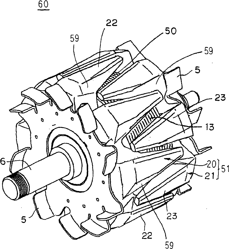
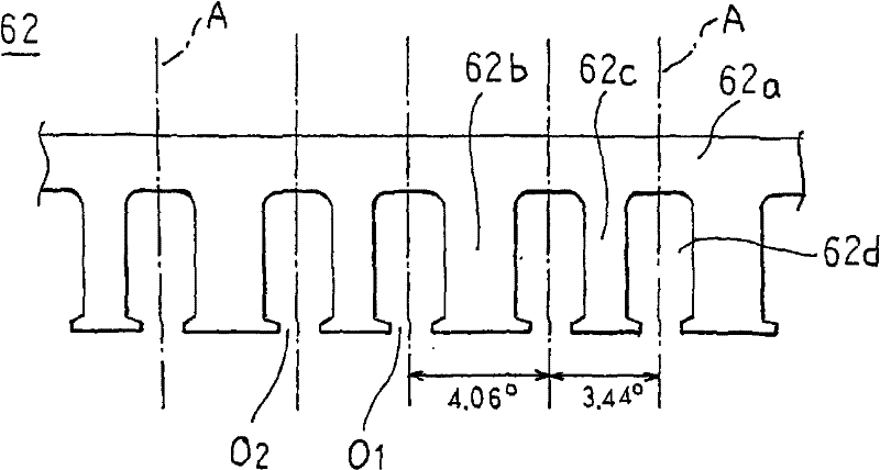
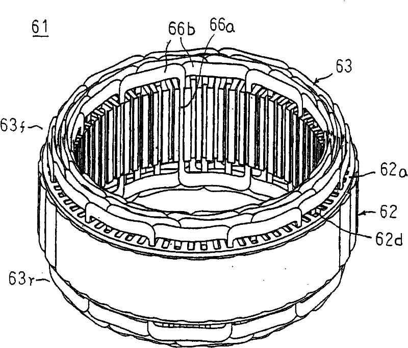
[0048] figure 1 Shown is a perspective view of a rotor of a vehicle alternator related to the present invention, figure 2 It is an explanatory drawing showing the stator core of the stator of the vehicle alternator related to the present invention flattened, image 3 Shown is a perspective view of a stator of a vehicle alternator related to the present invention, Figure 4 Shown is a side view of main parts of the stator of the vehicle alternator related to the present invention, Figure 5 It is a partial cross-sectional view showing the slot placement state of the stator winding of the stator of the alternator for vehicles related to the present invention, Image 6 It is an enlarged view of main parts of a stator winding part of a phase part of a stator of an alternator for a vehicle according to the present invention, Figure 7 It is a circuit diagram of the veh...


PUM


Abstract

The invention discloses an alternating-current generator used for vehicles. Grooves are formed on the stator core in a ratio of 2 per pole per phase. The stator winding is formed by a first three-phase stator winding and a second three-phase stator winding, which are wound around the stator core at an electrical angle of 30 DEG to 34 DEG. Each conducting wire forming the stator winding is provided with a slot accommodating part which is placed in a slot and shaped with a flat cross section. The slot accommodating parts are arranged in a row in the radial direction and placed inside the slot in a laminated manner. The coil ends of the stator winding and the slots are impregnated with the varnish paint.

Description

technical field [0001] The present invention relates to a vehicle alternator that generates an AC voltage in a stator by utilizing rotation of a rotor. Background technique [0002] Figure 16 is a longitudinal sectional view of a conventional vehicle alternator (hereinafter, simply referred to as an alternator), Figure 17 Shown is a perspective view of a rotor of a conventional generator, Figure 18 Shown is a perspective view of a stator of a conventional generator, Figure 19 For the circuit diagram of the conventional generator, Figure 20 Shown is a perspective view of a stator core of a conventional generator, Figure 21 It is an explanatory diagram for explaining the winding structure of the stator winding part of the one-phase part in the stator of the conventional generator. In addition, in Figure 18 In , the lead-out wire and neutral wire of the stator winding are omitted. [0003] exist Figure 16 to Figure 18 Among them, the generator has: a casing 3 com...

Claims


Application Information

Patent Timeline
Patent Type & Authority Patents(China)
IPC IPC(8): H02K19/26H02K3/12H02K3/28
Inventor 柏原利昭
Owner MITSUBISHI ELECTRIC CORP
Why Eureka
Try Eureka