Permanent magnet motor stator structure

A technology of stator structure and permanent magnet motor, applied in the direction of magnetic circuit shape/style/structure, magnetic circuit static parts, etc., can solve the problems of motor efficiency, mechanical overall strength, unsatisfactory performance, low mechanical performance, poor mechanical strength, etc. , to achieve the effect of ingenious design, simple structure and improved mechanical strength

Inactive Publication Date: 2012-11-28
SHANGHAI ZHONGKE SHENJIANG ELECTRIC VEHICLE
View PDF3 Cites 3 Cited by
  • Summary
  • Abstract
  • Description
  • Claims
  • Application Information

AI Technical Summary

Problems solved by technology

However, due to the unavoidable low mechanical performance of the single-tooth spliced ​​stator, the whole stator is shaken, the mechanical strength is relatively poor, and the strength is not enough. It is positioned and laminated with the corresponding structure on the stator yoke to form a stator core or a section
Its characteristic is that the individual teeth are directly connected on the inner side (air gap end), and the performance of the motor efficiency and the overall mechanical strength of the motor after splicing is not satisfactory

Method used


Image

  • Permanent magnet motor stator structure
  • Permanent magnet motor stator structure
  • Permanent magnet motor stator structure

Examples


Embodiment Construction

[0024] In order to understand the technical content of the present invention more clearly, the following examples are given in detail.

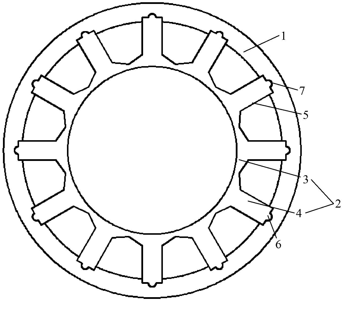
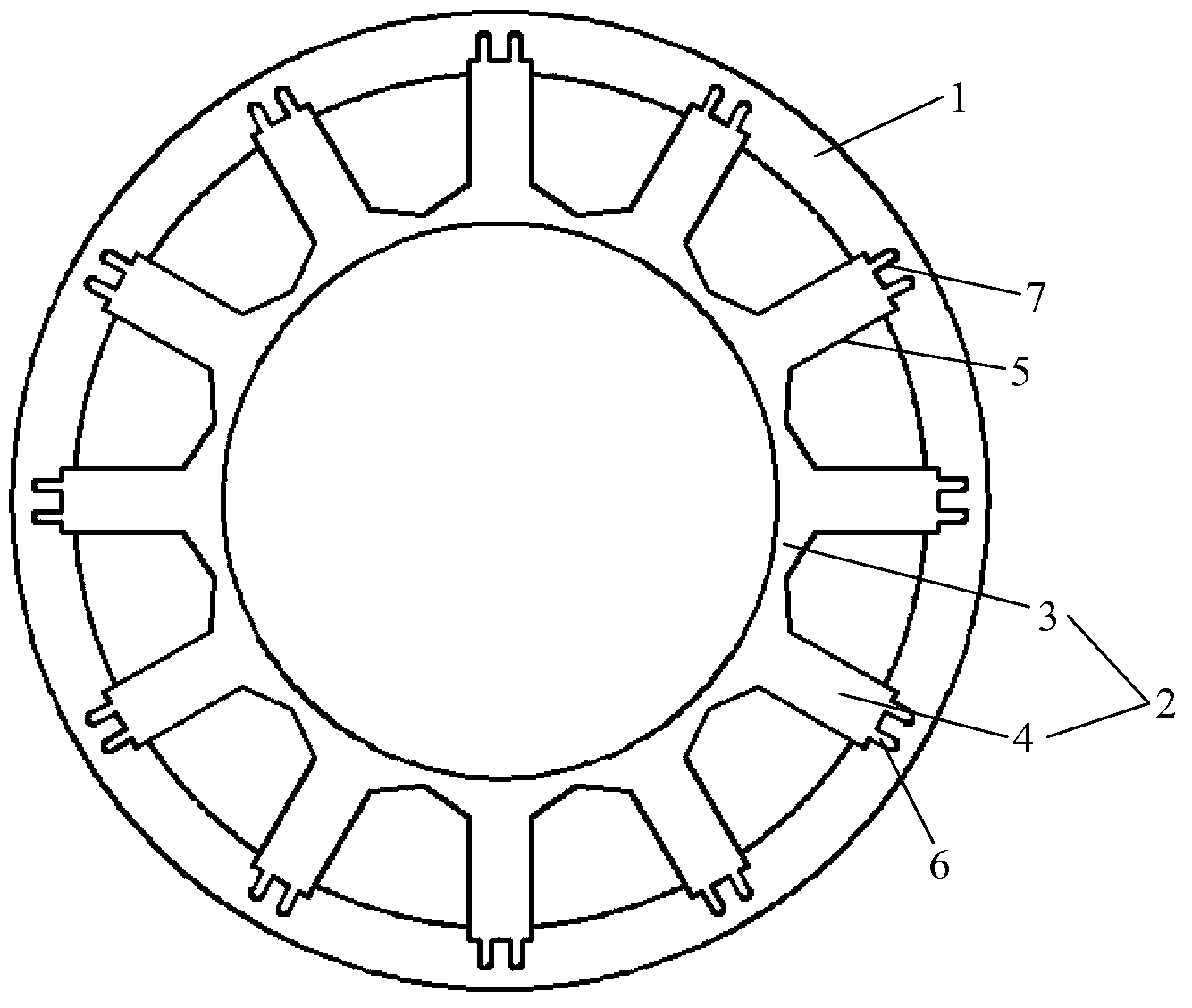
[0025] See Figure 2-Figure 4 As shown, the permanent magnet motor stator structure of the present invention includes a stator yoke 1 and a stator ring 2, and the stator ring 2 includes a ring base 3 and several stator teeth extending radially outward from the ring base 3 4. The stator yoke 1 is sleeved outside the stator gear ring 2, and the inner surface of the stator yoke 1 is provided with fixing grooves 5 having the same number as the stator teeth 4 and matching in shape. The stator teeth 4 are inserted in the fixing slots 5 and are in close contact with each other.

[0026] To further increase the contact area and reduce the effect on permanent magnet flux linkage, see Figure 2-Figure 4 As shown, in the first to third specific embodiments of the present invention, the top of the stator tooth 4 has a convex portion 6, and the bottom o...


PUM


Abstract

The invention relates to a permanent magnet motor stator structure which comprises a stator yoke part and a stator toothed ring, wherein the stator toothed ring comprises a ring base part and a plurality of stator teeth outwards extending from the radial direction of the ring base part, the stator yoke part is sleeved outside the stator toothed ring, and the inner surface of the stator yoke part is provided with fixed grooves which is same with the stator teeth in quantity and shape, the stator teeth are inserted in the fixed grooves and are mutually tightly contacted. Preferably, the tops of the stator teeth are provided with convex parts, the bottoms of the fixed grooves are provided with concave parts adapted to the convex parts in shapes, and the convex parts are inserted in the concave parts and are mutually tightly contacted. The stator yoke part is integrally formed, or is formed by connecting a plurality of sections. The ring base part is integrally formed or formed by connecting a plurality of sections. The permanent magnet motor stator structure has the advantages of being skilled in structure design and simple in structure, improving mechanical strength, lowering influence to a magnetic chain, and increasing the groove filling rate, thereby increasing the capacity and the efficiency of a motor, and the integral mechanical strength of the motor, and being suitable for being popularized and applied.

Description

technical field [0001] The invention relates to the technical field of motors, in particular to the technical field of permanent magnet motors, and specifically refers to a permanent magnet motor stator structure. Background technique [0002] Permanent magnet motor stators have various structures and slot shapes. As far as stators are concerned, there are conventional one-piece blanked full-piece stators as well as individual teeth such as figure 1 shown) spliced ​​stator. In some fields, due to the requirements of the application occasion, the whole stator is not suitable, and the spliced ​​stator made of single teeth is used. However, due to the unavoidable low mechanical performance of the single-tooth spliced ​​stator, the whole stator is shaken, the mechanical strength is relatively poor, and the strength is not enough. The corresponding structure on the stator yoke is positioned and laminated to form a stator core or a section. Its characteristic is that the indiv...

Claims


Application Information

Patent Timeline
Patent Type & Authority Applications(China)
IPC IPC(8): H02K1/16
Inventor 罗建朱勇
Owner SHANGHAI ZHONGKE SHENJIANG ELECTRIC VEHICLE
Why Eureka
Try Eureka