Single-winding low-cost high-power-density permanent magnet motor

A high power density, permanent magnet motor technology, applied in the direction of synchronous machines, electromechanical devices, electrical components, etc., can solve the problems of high cost of motor power inverter circuit, increase in the number of power switching devices, and increase the complexity of control circuits, etc., to achieve Good for heat dissipation, saving material consumption, and simple structure

Active Publication Date: 2015-12-30
SHANDONG UNIV
View PDF5 Cites 3 Cited by
  • Summary
  • Abstract
  • Description
  • Claims
  • Application Information

AI Technical Summary

Problems solved by technology

[0018] 1. The windings of existing permanent magnet motors are generally 3 phases, the number of stator slots is large, the winding process is complicated, and the manufacturing cost is high; the permanent magnets of most existing permanent magnet motors are located on the rotor and rotate with the rotor during operation. It needs to be fixed by a special process, and the manufacturing cost is high. Especially when the motor speed is high, it is more difficult to fix the permanent magnet. Since the permanent magnet is located on the rotor, it is difficult to dissipate heat during operation. The temperature rise and the vibration caused by the rotation of the rotor will cause the permanent magnet mechanical Structural damage and irreversible demagnetization
[0019] 2. Existing permanent magnet motors are generally three-phase, and the power inverter circuit of the motor requires at least 6 power switching devices, such as IGBT or MOSFET, as well as the corresponding driving circuit and protection circuit for driving the power switching devices. The cost of the motor power inverter circuit is quite high, even reaching two to three times the cost of the motor body. The increase in the number of power switching devices increases the complexity of the control circuit, increases the possibility of device failure, and reduces the reliability of the system during operation.
[0020] 3. Most of the existing permanent magnet motors have permanent magnets directly facing the air gap, and radially magnetized permanent magnets are required, because when parallel magnetization is used, the magnetic flux per pole of the motor will be significantly reduced, reducing the output and power density of the motor. However, the cost of radially magnetized permanent magnets is high, and it is very difficult to obtain uniform radially magnetized permanent magnets
[0021] 4. The amount of iron core used in the manufacture of existing permanent magnet motors is large, the mass of the motor is large, and the utilization rate of materials is low when the motor is running

Method used


Image

  • Single-winding low-cost high-power-density permanent magnet motor
  • Single-winding low-cost high-power-density permanent magnet motor
  • Single-winding low-cost high-power-density permanent magnet motor

Examples


Embodiment 1

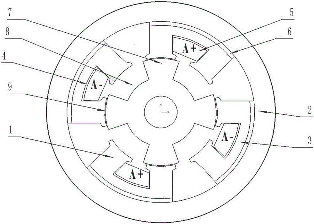
[0066] Example 1 as image 3 As shown, the number of teeth of the motor stator in this embodiment is 8, the number of teeth of the rotor is 4, and the number of permanent magnet blocks is 4. This embodiment includes a stator, a rotor and a main air gap, and the stator includes a stator core, a permanent magnet and a stator slot, and the stator iron The core includes stator teeth 1, stator back yoke 2 and stator slot yoke 3. The stator core is made of ferromagnetic material with high magnetic permeability. The stator core is provided with stator slots. The stator slots are armature slots 4 and armature slots 4 The armature winding 5 is placed inside, and the armature winding 5 penetrates through one armature slot and passes through another adjacent armature slot to form a coil, so that the current in each adjacent two armature slots has the same magnitude , the direction is opposite; there is an arc-shaped permanent magnet 6 between the stator slot yoke 3 and the stator back yo...

Embodiment 2

[0068] Example 2 as Figure 4 As shown, the number of stator teeth of the motor in this embodiment is 8, the number of teeth of the rotor is 4, and the number of permanent magnet blocks is 12. This embodiment includes a stator, a rotor, and a main air gap. The core includes stator teeth 1, stator back yoke 2 and stator slot yoke 3. The stator core is made of ferromagnetic material with high magnetic permeability. The stator core is provided with stator slots. The stator slots are armature slots 4 and armature slots 4 The armature winding 5 is placed inside, and the armature winding 5 penetrates through one armature slot and passes through another adjacent armature slot to form a coil, so that the current in each adjacent two armature slots has the same magnitude , the direction is opposite; arc-shaped permanent magnets 6 are placed between the stator slot yoke 3 and the stator back yoke 2, and there are 3 permanent magnets on each stator slot yoke 3, and the permanent magnets ...


PUM


Abstract

The invention discloses a single-winding low-cost high-power-density permanent magnet motor which is characterized by comprising a stator and a rotor, wherein the stator comprises a stator yoke composed of a stator back yoke and a plurality of stator slot yokes; a permanent magnet is arranged between the stator back yoke and each stator slot yoke; a stator tooth is arranged at each of the two ends of each stator slot yoke; an armature slot is formed between every two stator teeth; a set of armature winding is arranged in each armature slot; the rotor comprises a plurality of rotor teeth; a rotor slot is formed between every two adjacent rotors; a main air gap is formed between each rotor tooth and the corresponding stator teeth. The single-winding low-cost high power-density permanent magnet motor is simple in manufacturing technique and low in cost.

Description

technical field [0001] The invention relates to a permanent magnet motor, in particular to a permanent magnet motor with single winding, low cost and high power density. Background technique [0002] In recent years, with the improvement of high temperature resistance and price reduction of permanent magnet materials, permanent magnet motors have been more widely used in national defense, industrial and agricultural production, and daily life, and are moving towards high power, high performance and miniaturization. direction of development. At present, the power of permanent magnet motors ranges from a few milliwatts to several thousand kilowatts, and its application ranges from toy motors, industrial applications to large permanent magnet motors for ship traction, and has been widely used in various aspects of the national economy, daily life, military industry, and aerospace. widely used. The main applications are as follows: [0003] (1) Household appliances: including...

Claims


Application Information

Patent Timeline
Patent Type & Authority Applications(China)
IPC IPC(8): H02K21/00H02K1/17
Inventor 王道涵
Owner SHANDONG UNIV
Why Eureka
Try Eureka