A lobe split combination stator

A technology of combining stators and lobes, applied in the shape/pattern/structure of electric components, winding conductors, magnetic circuit shape/pattern/structure, etc. The problem of low utilization rate, etc., can reduce vibration and noise, fix firmly, and reduce the cost of mold input.

Pending Publication Date: 2019-01-18
GUANGDONG HEPU POWER TECH
View PDF0 Cites 1 Cited by
  • Summary
  • Abstract
  • Description
  • Claims
  • Application Information

AI Technical Summary

Problems solved by technology

[0003] 1. The slot of the stator must be large, and the torque ripple and noise are relatively large;
[0004] 2. The slot full rate generally does not exceed 50%, and the motor volume is relatively large;
[0005] 3. The enameled wire must pass through the notch o

Method used


Image

  • A lobe split combination stator
  • A lobe split combination stator
  • A lobe split combination stator

Examples


Embodiment Construction

[0021] The present invention will now be described in further detail with reference to the drawings and embodiments:

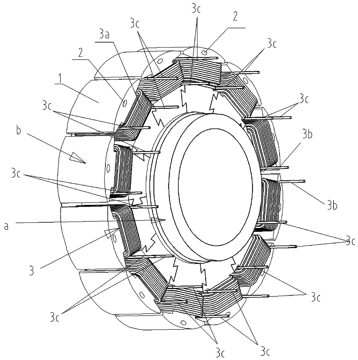
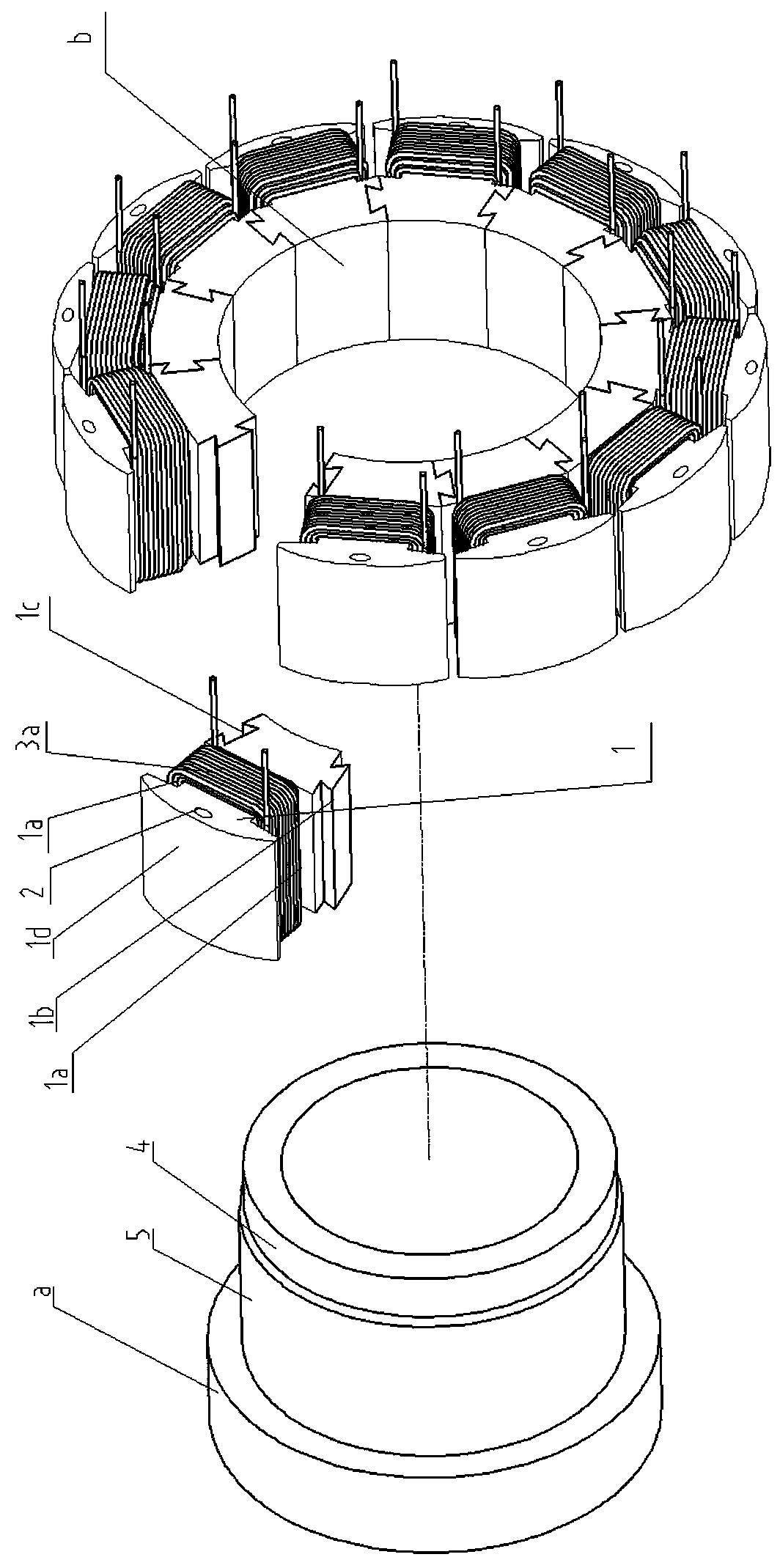
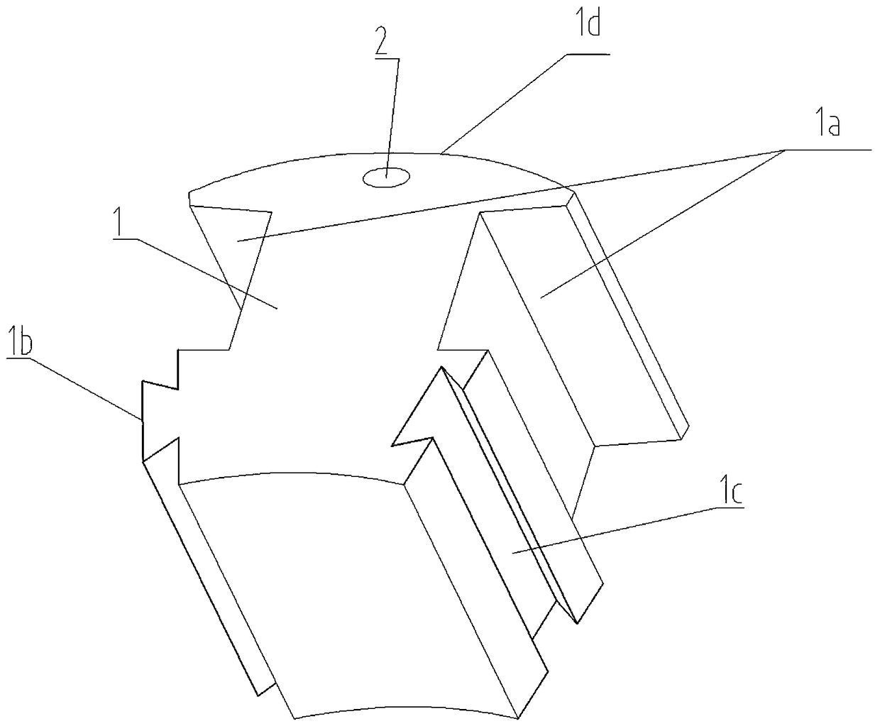
[0022] Such as figure 1 As shown in —3, the present invention includes a ring-shaped expansion sleeve a, a ring-shaped stator core b formed by connecting several fan-shaped iron core units 1 in series with each other. The fan-shaped iron core unit 1 is composed of several punched sheets laminated together The two sides of the fan-shaped core unit 1 are provided with grooves 1a in the middle, and the grooves 1a are used to wind the stator coil 3. The two sides of the lower part of the fan-shaped core unit 1 are respectively provided with tenons 1b and grooves 1c. The iron core unit 1 is inlaid with each other through the tenon 1b and the tenon groove 1c. A certain number of fan-shaped split fan-shaped iron core units 1 are combined to form an annular stator iron core b, and the groove 1a of the fan-shaped iron core unit 1 is wound There are stator coil windings 3...


PUM


Abstract

A lobe split combination stator includes an annular expansion sleeve, an annular stator iron core formed by a plurality of sector iron core units connected in series with each other, the middle of both sides of the sector core unit is provided with grooves, the two sides of the lower part of the sector-shaped iron core unit are respectively provided with a tenon and a tenon groove, As that two adjacent sector core unit are are inlaid with each other to form an annular stator core through the tenon, and grooves;, the stator coil windings with several turns are wound on the grooves of each sector-shaped iron core unit by wires, and then adjacent sector-shaped iron core units are embedded together to form an annular stator core wound with the stator coils, and the annular expansion sleeve interference mosaic is embedded into the combined annular stator core inner hole. Compared with the prior art, The invention has the advantages that the stator notch need not be very large, the slot full rate is high, the relative volume of the motor is small, the enameled wire can be effectively avoided from touching the notch, the material utilization rate is high, the torque ripple and the noiseare low.

Description

Technical field [0001] The invention relates to a permanent magnet synchronous motor and a generator with an outer rotor structure, in particular to the field of low-speed, multi-pole motors. Background technique [0002] With the development of society, labor costs are getting higher and higher. The motor stator urgently needs to be transformed from manual wire embedding to machine wire embedding. Most of the automatic wire embedding adopts integral iron core and concentrated winding, and the winding adopts flying fork winding method, especially It is a stator with a relatively large volume and weight. Almost all stator cores are fixed and flying fork winding is used. This kind of stator structure is shown in Figure 4 , The disadvantages of this stator and winding method: [0003] 1. The stator slot must be large, and the torque ripple and noise are relatively large; [0004] 2. The slot full rate generally does not exceed 50%, and the motor volume is relatively large; [0005] 3. T...

Claims


Application Information

Patent Timeline
IPC IPC(8): H02K1/18H02K1/14H02K3/18
CPCH02K1/14H02K1/187H02K3/18H02K2201/15
Inventor 梁昌勇李显平李红文杨良才
Owner GUANGDONG HEPU POWER TECH
Why Eureka
Try Eureka