Method and system for synchronizing clock of transmission network as well as subordinate clock side entity

A clock synchronization and transmission network technology, applied in the field of transmission network, can solve problems such as inaccurate results and inability to guarantee clock synchronization, and achieve the effect of accurate clock synchronization

Active Publication Date: 2008-12-24
DATANG MOBILE COMM EQUIP CO LTD
View PDF0 Cites 48 Cited by
  • Summary
  • Abstract
  • Description
  • Claims
  • Application Information

AI Technical Summary

Problems solved by technology

[0018] The object of the present invention is to provide a clock synchronization method, system and slave clock side entity in a transmission network, to overco

Method used


Image

  • Method and system for synchronizing clock of transmission network as well as subordinate clock side entity
  • Method and system for synchronizing clock of transmission network as well as subordinate clock side entity
  • Method and system for synchronizing clock of transmission network as well as subordinate clock side entity

Examples


no. 1 example

[0272] Firstly, the first embodiment of the system of the present invention is introduced, and the system embodiment corresponds to the first embodiment of the aforementioned method. Figure 10 A block diagram of an embodiment of the system is shown.

[0273] A clock synchronization system in a transmission network, comprising a master clock side 101 and a slave clock side 102, where the master clock side 101 is used for message interaction with the slave clock side 102;

[0274] The slave clock side 102 includes a clock measurement message interaction unit 1021, an external detection unit 1022, a clock difference calculation unit 1023 and a clock adjustment unit 1024, wherein,

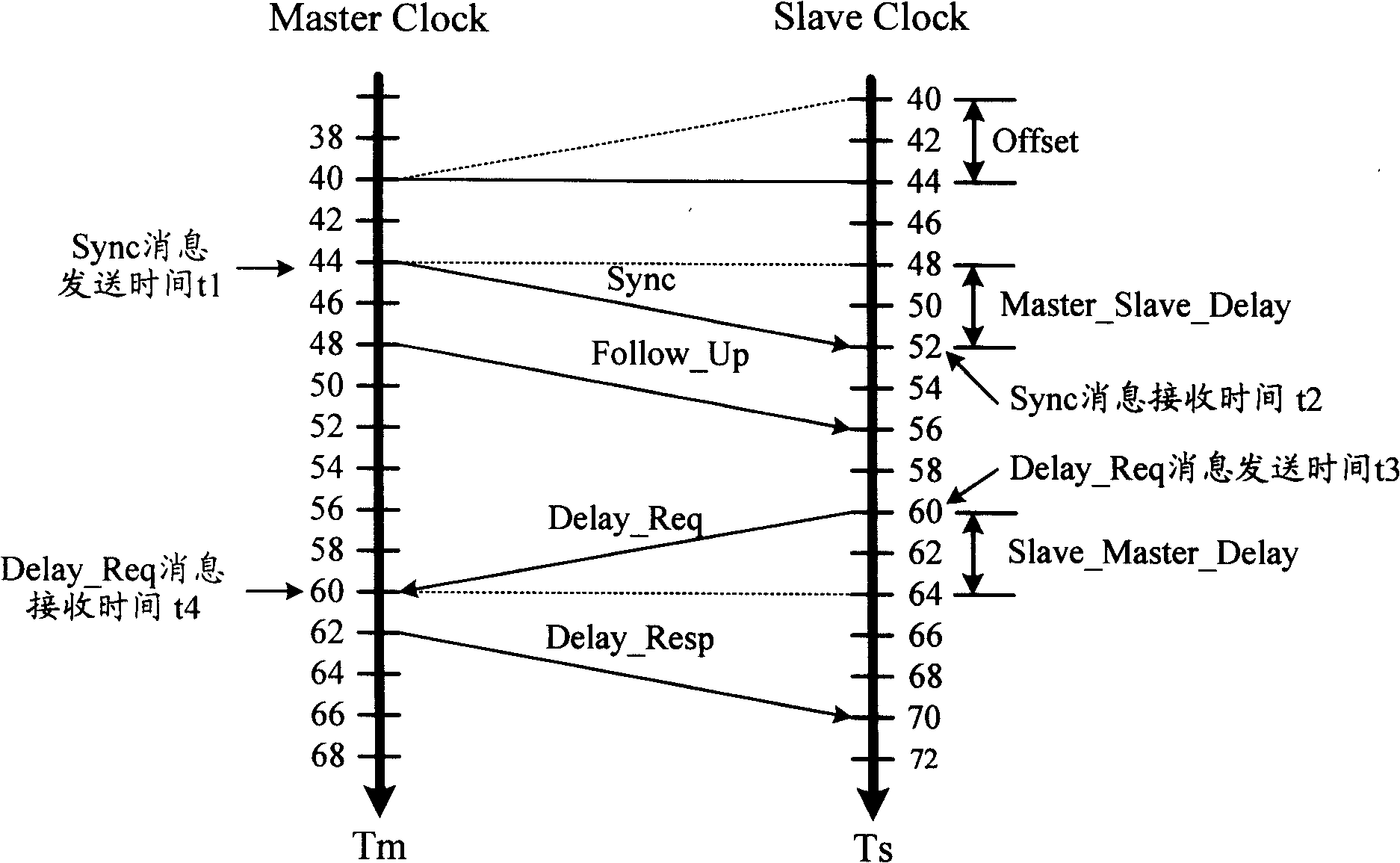
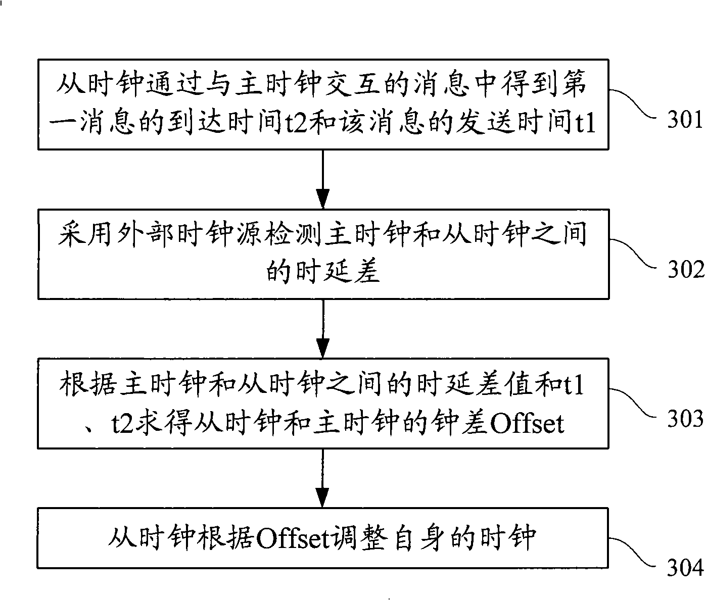
[0275] A clock measurement message interaction unit 1021, configured to obtain the arrival time t2 of the first message and the sending time t1 of the message through message interaction with the main clock side 101;

[0276] The external detection unit 1022 is used to detect the delay between the ma...

no. 3 example

[0304] The third embodiment of the system of the present invention is introduced below, and the system embodiment corresponds to the third embodiment of the aforementioned method. Figure 12 A block diagram of an embodiment of the system is shown.

[0305] A clock synchronization system in a transmission network, comprising a master clock side 111, a slave clock side 122, a network element delay difference detection unit 123, and a network management center 124, and the master clock side 111 is used for message interaction with the slave clock side 122;

[0306] The slave clock side 122 includes a clock measurement message interaction unit 1221, a clock difference calculation unit 1222 and a clock adjustment unit 1223, wherein,

[0307] The clock measurement message interaction unit 1221 is configured to obtain the arrival time t2 and sending time t1 of the first message through message interaction with the master clock, and obtain the arrival time t4 and sending time t3 of th...


PUM


Abstract

The invention discloses a clock synchronization method in a transmission network. The method comprises the steps of obtaining the arrival time t2 and the sending time t1 of first message through the interaction of a slave clock and a master clock; adopting external clock source to detect the time delay of the master clock and the salve clock; seeking clock error Offset according to the time delay between the master clock and the slave clock, t1 and t2; and adjusting the clock of the slave clock according to Offset. The invention further discloses a clock synchronization method in other two transmission networks, and also discloses a clock synchronization system of three transmission networks. The clock synchronization method of the invention can accurately calculate clock error Offset, thereby ensuring the synchronization of the slave clock and the master clock.

Description

technical field [0001] The present invention relates to the field of transmission network technology, in particular to a clock synchronization method and system in a transmission network and a slave clock side entity. Background technique [0002] The purpose of synchronization is to keep two or more signals consistent in time, specifically, to keep strictly consistent in frequency or phase. Clock synchronization methods include master-slave synchronization. In this way, the timing signal is transmitted from the master clock to the subordinate slave clock, and the slave clock adjusts its own clock according to the obtained timing signal to maintain synchronization with the master clock. [0003] In the clock synchronization method of a master-slave synchronization method in the prior art, the message sending process is as follows: figure 1 shown. It can be seen from the figure that Tm is the master clock, and Ts is the slave clock. The master clock and the slave clock are...

Claims


Application Information

Patent Timeline
IPC IPC(8): H04L7/02
Inventor 谢子阳文志刚王洪波李军
Owner DATANG MOBILE COMM EQUIP CO LTD
Why Eureka
Try Eureka