Safe wrench structure

A safety wrench and shaft technology, applied in the direction of wrenches, screwdrivers, manufacturing tools, etc., can solve the problems of operators falling, breaking, poor practicability, etc., to avoid the effect of losing the center of gravity and falling

Inactive Publication Date: 2008-12-31
谢智庆
View PDF0 Cites 0 Cited by
  • Summary
  • Abstract
  • Description
  • Claims
  • Application Information

AI Technical Summary

Problems solved by technology

[0005] However, although this kind of wrench slipping device can be tightly sleeved with the fixing part to prevent the risk of slipping, it ignores the limit torque value that the wrench body can bear, and each component on the wrench also has its limit strength, especially when When operating some operations that require a large torque to lock firmly, if the ratchet in the wrench exceeds the limit torque value it can withstand, it is prone to "rapid chipping" and the ratchet due to If the operator is in the situation of pulling the wrench vigorously at this time, it is easy to fall due to the instantaneous disappearance of the clamping force, which is even more dangerous for the more dangerous job sites. When working at a place, if you accidentally lose your center of gravity and fall, causing your head to be bumped or dropped from a high place, it will cause irreparable shortcomings; even if the head of the wrench can withstand a large torque, the neck or handle can withstand When the limit torque value is smaller than the head, if a huge torque is applied at this time, although the head of the wrench will not slip off, the wrench may suddenly break due to a large amount of stress concentrated on the weak surface of the neck or handle Naturally, it is easy for the operator to suddenly lose the center of gravity and fall down, and even the broken wrench falls off from the hand and hurts nearby personnel. Therefore, overall, its practicability is poor, and there is still a need for improvement.

Method used


Image

  • Safe wrench structure
  • Safe wrench structure
  • Safe wrench structure

Examples


Embodiment Construction

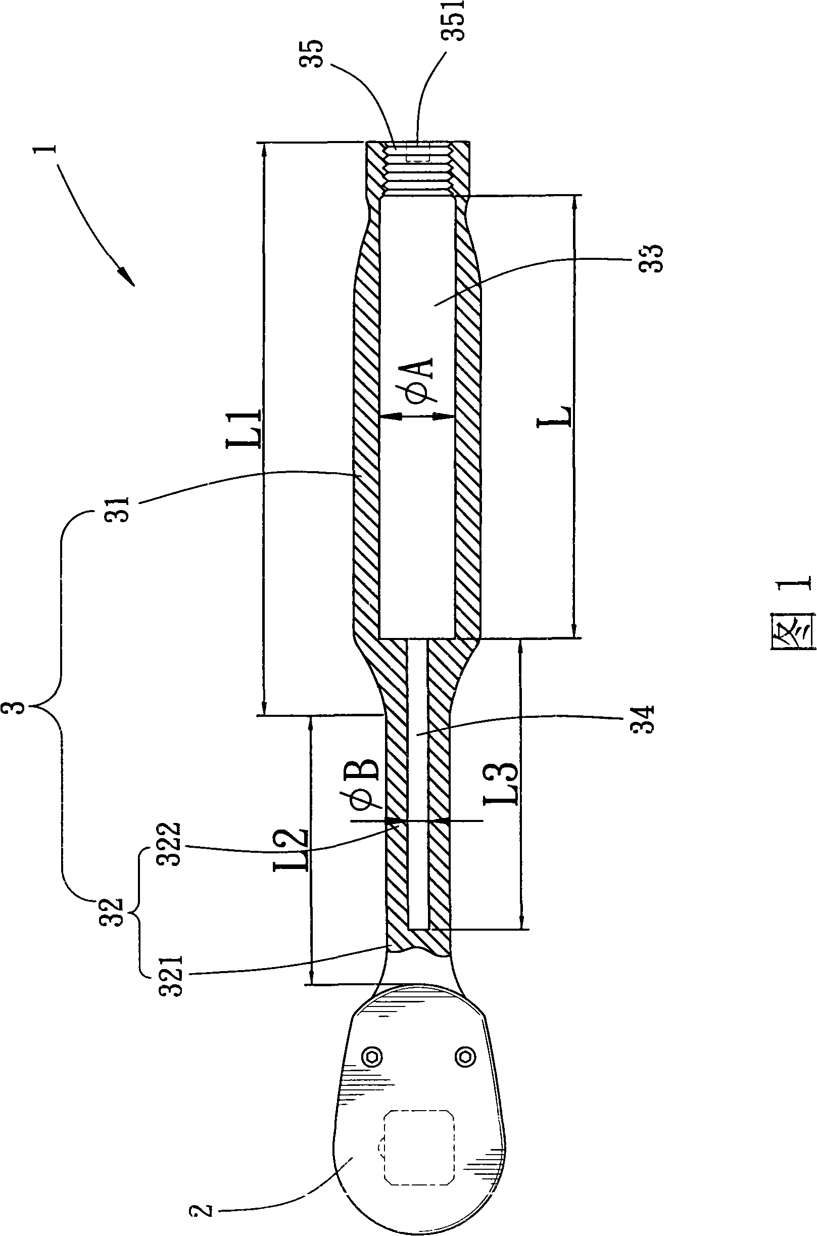
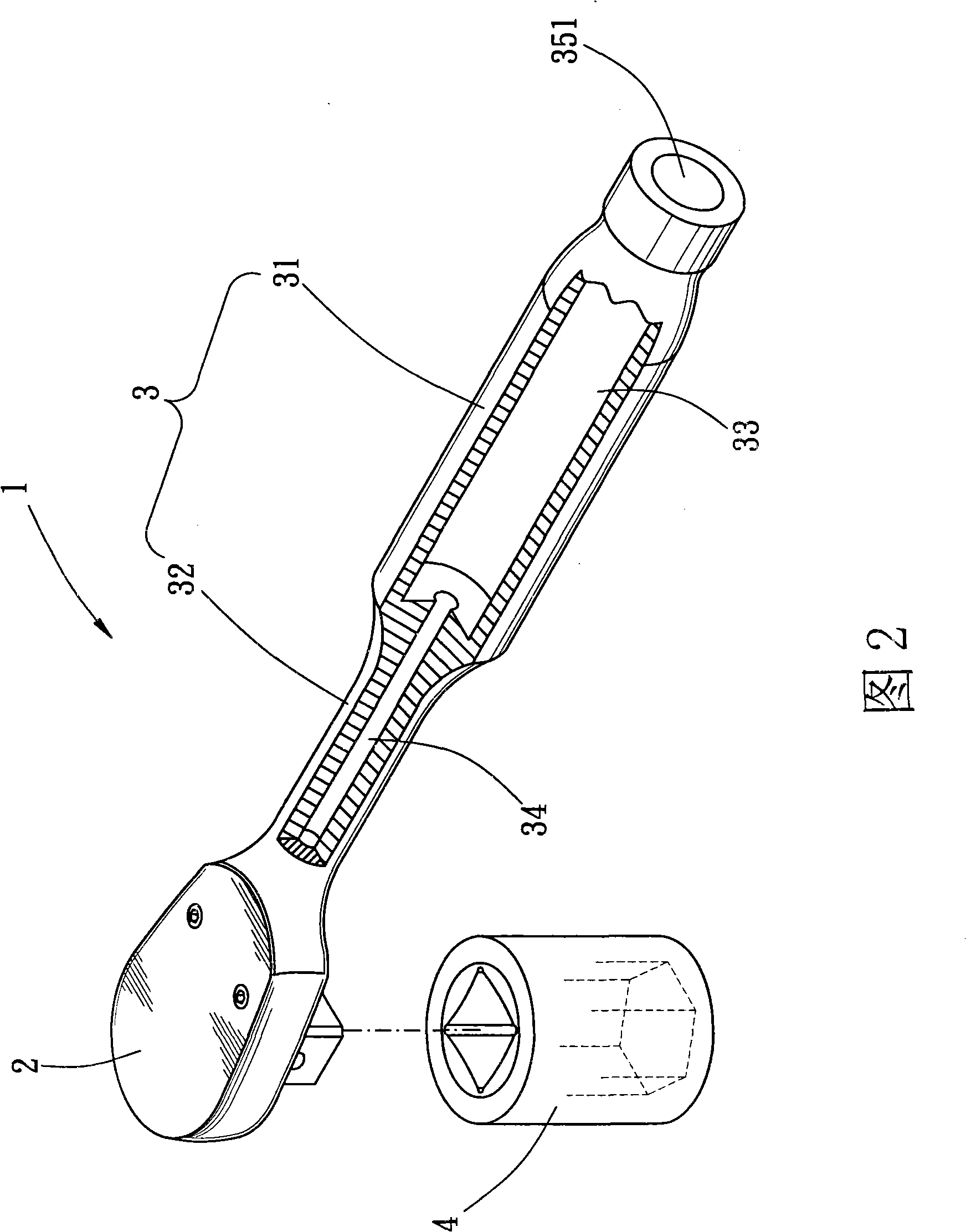
[0029] The present invention relates to a safety wrench structure, please refer to Fig. 1 and Fig. 2, its body 1 includes a head 2 and a handle 3, wherein:

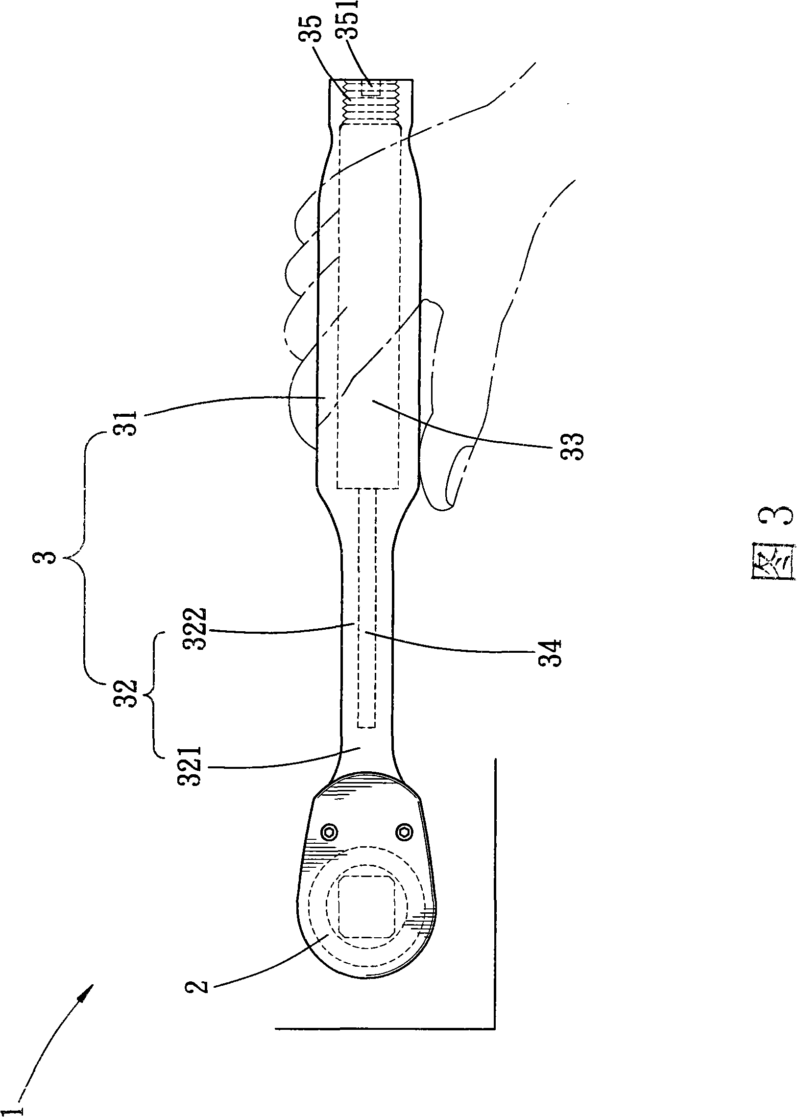
[0030] The head 2 is provided with a fixing part 4 for locking, and it is connected with the handle 3, so that when the head 2 and the fixing part 4 are locked, the user applies force on the end of the handle 3 opposite to the head 2, and Make the body 1 generate torque with the head 2 as the fulcrum, so that the fixing part 4 is locked into the object along the rotation direction of the torsion force, and at this time the fixing part 4 also returns the reaction torque to the body 1, and causes a shear force on the body 1 and torque;

[0031] The handle 3 is assembled with the head 2, and the handle 3 has a first shaft 31 and a second shaft 32, the first shaft 31 is thicker than the second shaft 32, the first shaft The joint between the body 31 and the second shaft 32 is tapered toward the second shaft 32 and is thicker ...


PUM


Abstract

The invention discloses a safe spanner structure, a spanner body thereof mainly comprises a head part and a handle part, the head part is connected with the handle part, and the handle part comprises a first rod body and a second rod body, the first rod body is thicker than the second rod body, the length of first rod body is defined as L1 and the length of the second rod body is defined as L2; a first space and a second space are arranged inside the handle part, the first space and the second space are intercommunicated, the length and the inner diameter of the first space are defined as L and Phi A respectively, the length and the inner diameter of the second space are defined as L3 and Phi B respectively; L1 is more than L, L2 is more than L3, and Phi A is more than Phi B; owing to the first space and the second space which are arranged at the handle part, the body is light and in a non-solid state, so slow flexure effect is produced after an excess force application, which can warn the users to protect safety. The safe spanner structure prevents the users from falling off caused by losing balance owing to the application of a force when the body is to be damaged.

Description

technical field [0001] The invention relates to a safety wrench structure. Background technique [0002] The design of the wrench is that the front end of the handle has a head that is embedded with the fixing part, so that a force is applied at the handle to generate a torque to drive the head to screw the fixing part into the object, so that the threaded part of the fixing part is locked into the object. When using this kind of torque wrench, in addition to the torque applied to the wrench varies from person to person, the torque required for different operations is also different, but the torque that the wrench can withstand Or the clamping effect is limited. If the wrench is poorly designed or the user uses too much force when operating, the wrench may suddenly slip off from the fixing part and cause danger. Therefore, some companies have designed an anti-loosening device for the wrench. [0003] For the existing wrench anti-off device, please refer to China Taiwan Anno...

Claims


Application Information

Patent Timeline
Patent Type & Authority Applications(China)
IPC IPC(8): B25B23/16
Inventor 谢智庆
Owner 谢智庆
Why Eureka
Try Eureka