Single-block fluid injection device and production and control method thereof

A technology of fluid jetting and jetting device, applied in printing and other directions, which can solve the problems of inability to control the direction of ink droplets, increasing nozzle holes, and poor printing quality.

Inactive Publication Date: 2008-12-31
BENQ CORP
View PDF0 Cites 3 Cited by
  • Summary
  • Abstract
  • Description
  • Claims
  • Application Information

AI Technical Summary

Problems solved by technology

Known fluid ejection devices suffer from poor print quality due to inability to precisely control the ejected ink volume of the ink droplets
Moreover, the known fluid ejection device cannot control the direction of the ejected ink droplets, therefore, if the resolution is to be improved, the number of nozzle holes will be increased, resulting in increased manufacturing cost

Method used


Image

  • Single-block fluid injection device and production and control method thereof
  • Single-block fluid injection device and production and control method thereof
  • Single-block fluid injection device and production and control method thereof

Examples


Embodiment Construction

[0027] Next, detailed description will be given in conjunction with the accompanying drawings, so as to better understand the fluid ejection device and its manufacturing and control methods in the preferred embodiments of the present invention. It can be appreciated, however, that the present invention provides many inventive concepts that can be implemented in a wide variety of fields of application. The illustrative examples are merely illustrations of specific implementations utilizing the concepts of the present invention and do not limit the scope of the present invention.

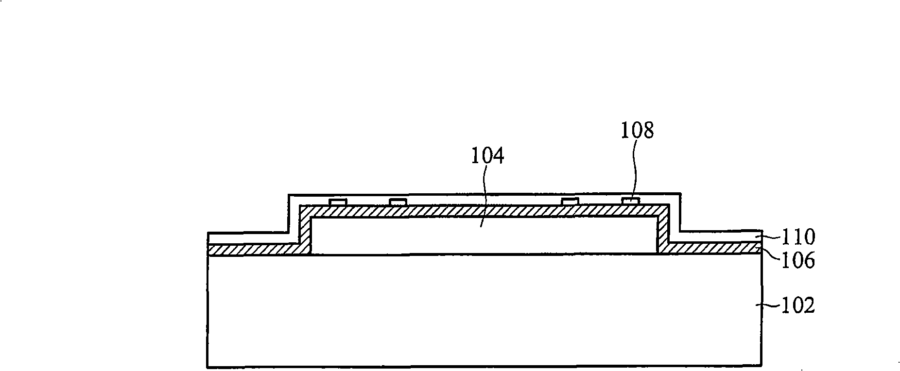
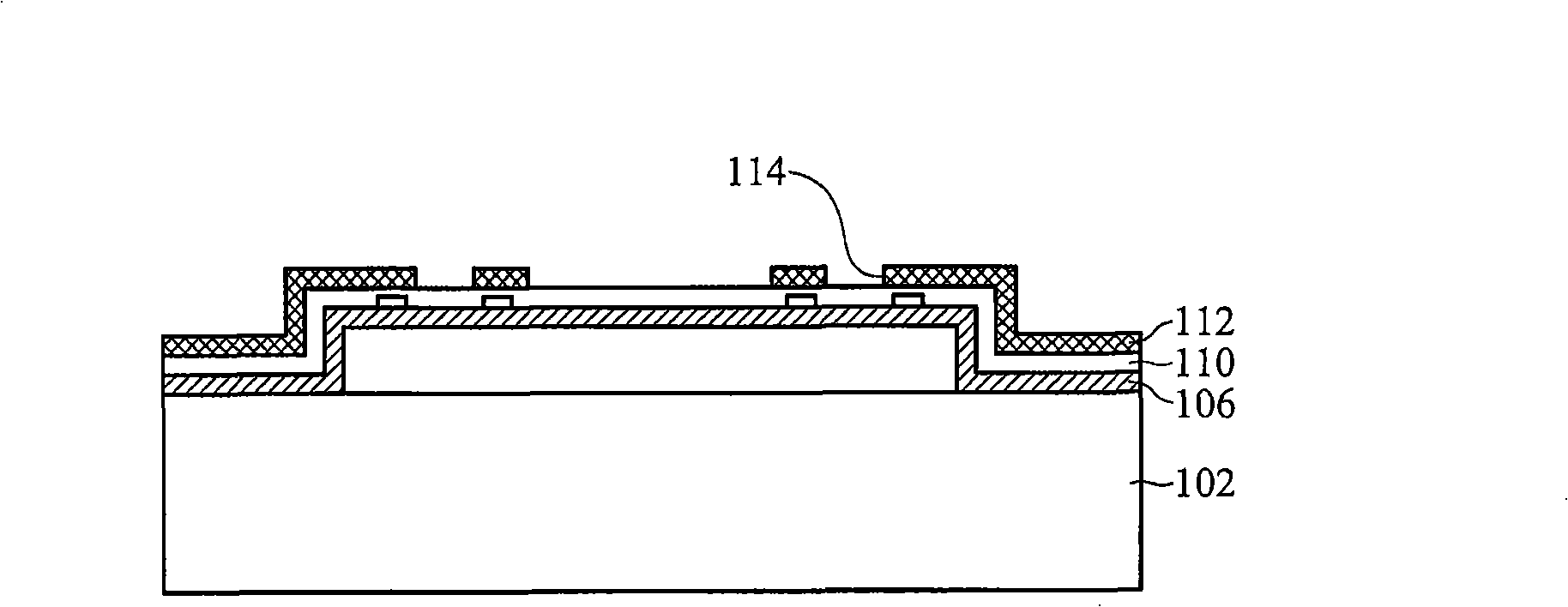
[0028] Figure 2A-Figure 2E A cross-sectional view of fabricating a monolithic fluid ejection device according to an embodiment of the invention is shown. Figure 2F A schematic bottom view showing an orifice of a monolithic fluid ejection device according to an embodiment of the present invention.

[0029] refer to Figure 2A , providing a substrate 102 , such as a monocrystalline silicon substrat...


PUM


Abstract

The invention provides a single block fluid injection device and a preparation and control method of the single block fluid injection device. The single block fluid injection device comprises a substrate, a structure layer which is arranged on the substrate; furthermore, a fluid chamber is formed between the structure layer and the surface of the substrate, so as to receive the fluid; the single block fluid injection device also comprises a liquid surface control unit which is formed on the structure layer and an injection hole which passes through the liquid surface control unit and the structure layer, so as to be communicated with the fluid chamber. The liquid surface height of the fluid in the injection hole is regulated by the liquid surface control unit, so as to inject the ink drops with different fluxes and directions.

Description

technical field [0001] The invention relates to a monolithic fluid ejection device, in particular to a monolithic fluid ejection device with different liquid level heights in spray holes and its manufacturing and control method. Background technique [0002] Due to continuous breakthroughs and innovations in the printing technology of liquid jet printers, the requirements for printing quality and resolution have also been continuously improved. In general, the print quality and resolution of liquid jet printers are determined by the amount of ink jetted and the drop point of jetted ink droplets. [0003] figure 1 is a known monolithic fluid ejection device 1 . exist figure 1 In the present invention, a structural layer 12 is formed on a silicon substrate 10 , and a first heater 16 and a second heater 18 are formed above the structural layer 10 . another example figure 1 As shown, then, a fluid cavity 14 is formed between the structural layer 10 and the silicon substrate...

Claims


Application Information

Patent Timeline
Patent Type & Authority Applications(China)
IPC IPC(8): B41J2/14B41J2/04B41J2/05
Inventor 周忠诚王威
Owner BENQ CORP
Why Eureka
Try Eureka