Body motion detection device
The technology of a detection device and a detection part, which is applied in the field of pedometers, can solve the problems of increased manufacturing cost, complicated device structure, and difficult manufacturing, and achieve the effect of preventing the decline of measurement accuracy
- Summary
- Abstract
- Description
- Claims
- Application Information
AI Technical Summary
Problems solved by technology
Method used
Image


Examples
no. 1 approach
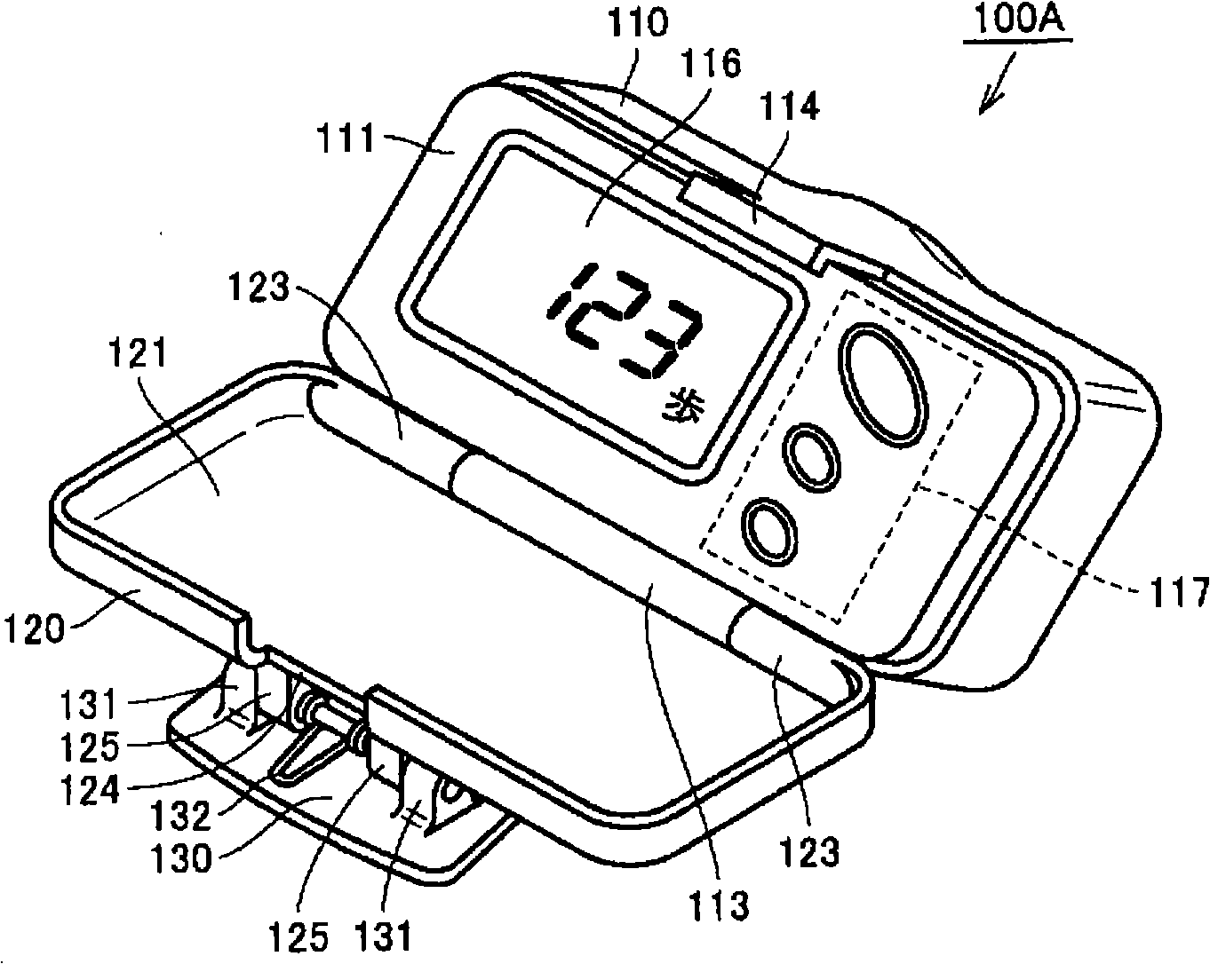
[0116] figure 1 as well as figure 2 is a diagram showing the appearance structure of the pedometer according to the first embodiment of the present invention, wherein figure 1 is a schematic perspective view of the pedometer when it is turned on, figure 2 is the side view with the pedometer turned on. in addition, image 3 It is a figure which shows the internal structure of the pedometer of this embodiment, and is a schematic side view when the pedometer is closed. First, with reference to these figures, the external structure and internal structure of the pedometer according to this embodiment will be described.
[0117] like figure 1 as well as figure 2 As shown, the pedometer 100A of this embodiment has a portable small main body case, and the main body case is divided into a case main body 110 , a cover body 120 , and a clip body 130 .
[0118] The box main body 110 has a display surface 111, on which a display portion 116 and an operation portion 117 are provid...
no. 2 approach
[0146] Figure 10 is a diagram showing the internal structure of the pedometer according to the second embodiment of the present invention, and is a schematic side view when the pedometer is in a closed state. In addition, FIG. 11 is a diagram showing an assembly structure in which the pedometer according to the present embodiment is assembled on the printed circuit board of the sensor unit. here, Figure 11A is a schematic perspective view of the assembled printed circuit board, Figure 11B as well as Figure 11C A front view and a side view of the assembled printed circuit board, respectively. In addition, about the same part as pedometer 100A of said 1st Embodiment, the same code|symbol is attached|subjected in drawing, and the description is not repeated here.
[0147] like Figure 10 As shown, the pedometer 100B of this embodiment is the same as the pedometer 100A of the above-mentioned first embodiment. A printed circuit board 140 serving as a circuit board is hous...
no. 4 approach
[0180] Figure 20 is a diagram showing the internal structure of the pedometer according to the fourth embodiment of the present invention, and is a schematic side view of the pedometer in a closed state. In addition, FIG. 21 is a diagram showing an assembly structure in which the pedometer according to the present embodiment is assembled on the printed circuit board of the sensor unit. here, Figure 21A is a schematic perspective view of the assembled printed circuit board, Figure 21B as well as Figure 21C A front view and a side view of the assembled printed circuit board, respectively. In addition, about the same part as pedometer 100C of said 3rd Embodiment, the same code|symbol is attached|subjected in drawing, and the description is not repeated here.
[0181] like Figure 20 As shown, the pedometer 100D of this embodiment is the same as the pedometer 100C of the above-mentioned third embodiment. A printed circuit board 140 serving as a circuit board is housed an...
PUM
 Abstract
Description
Claims
Application Information