Lifting and hoisting method of vertical equipment

A hoisting method and vertical equipment technology, applied in the direction of transportation and packaging, load hanging components, etc., can solve the problem of single function of the rotating shaft system, and achieve the effect of convenient and flexible operation, flexible operation and good operability

Active Publication Date: 2009-01-07
SINOPEC NINGBO ENG
View PDF0 Cites 25 Cited by
  • Summary
  • Abstract
  • Description
  • Claims
  • Application Information

AI Technical Summary

Problems solved by technology

To sum up, the function of the shaft system is single and the structure is relatively simple when hoisting vertical equipment by the usual push method and turning method

Method used


Image

  • Lifting and hoisting method of vertical equipment
  • Lifting and hoisting method of vertical equipment
  • Lifting and hoisting method of vertical equipment

Examples


Embodiment Construction

[0034] The present invention will be further described in detail below in conjunction with the accompanying drawings and embodiments.

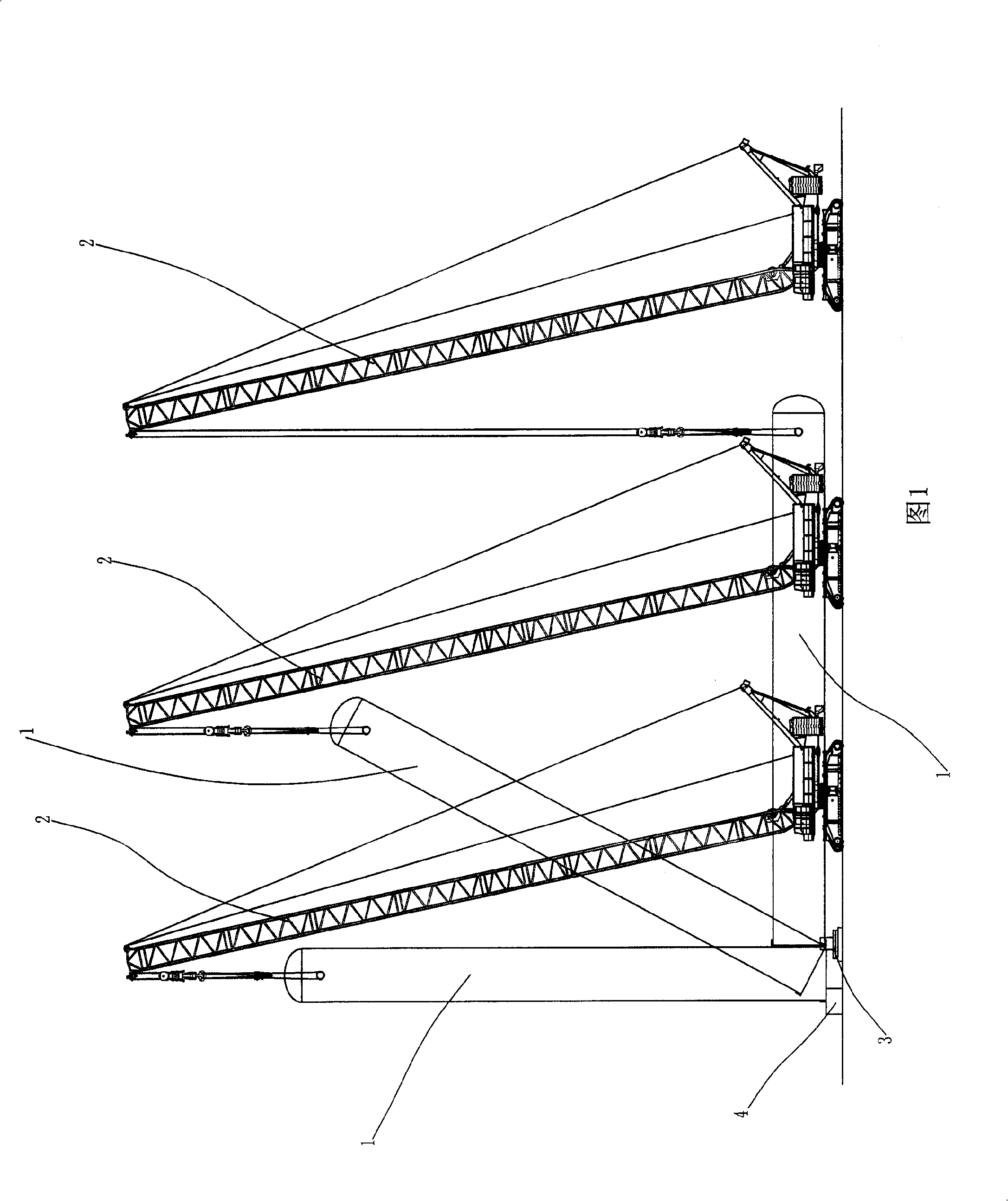
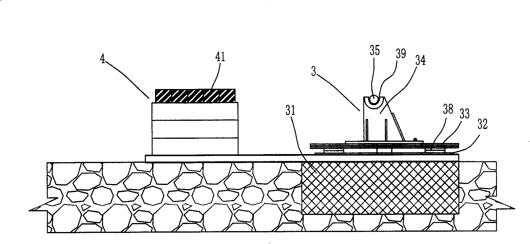
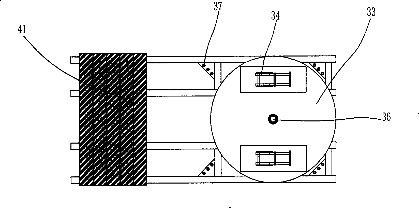
[0035] In the present embodiment, the rotating shaft system 3 and the anti-tilt facility 4 are first set, such as Figure 2 to Figure 3 As shown, the underground foundation 31 is first set up underground. The underground foundation 31 in this embodiment adopts a concrete cap, and the chassis 32 is fixed on the underground foundation 31 by bolts 37 . The turntable 38 is circular and includes an upper turntable and a lower turntable, the lower turntable is fixed on the chassis 32, the lower turntable is fixed on the carrier plate 33 above it, and the upper turntable and the lower turntable are formed by bearing connection A matching structure that can rotate around the vertical axis of rotation 36. Two horizontal shaft bearings 34 are fixedly installed on the bearing plate 33, and a shaft hole 39 is formed on the top of the horizontal shaft bra...


PUM


Abstract

The invention relates to a method for lifting and hoisting vertical equipment, which is characterized in that the method comprises the following steps: a) the equipment to be hoisted is unloaded according to the on-site conditions for hoisting, and the placement of the equipment is not restricted by the position of an equipment base; b) a rotating shaft system is arranged at the bottom of the equipment, and an inclination prevention facility is arranged in the position where the equipment reaches an inclination prevention angle; c) the hoisting point of the equipment is connected with the drop hanger of a hoist, and the hoisting point is located above the gravity center of the equipment; d) the hoist lifts the drop hanger and travels forward or turns around so as to cause the equipment to rotate around a rotating shaft system and gradually erect; e) when the equipment reaches the position of the inclination prevention angle, the equipment continues to rotate around the inclination prevention facility till the equipment completely erects; and f) the drop hanger of the hoist is lifted continually to separate the equipment from the inclination prevention facility, the rotating shaft is removed, the equipment is rotated to the equipment base, and the orientation is adjusted to cause the equipment to be in place. The method does not need to use a pulley block and has no restrictions on the orientation of the hoisting point; the operation is convenient and flexible.

Description

technical field [0001] The invention relates to the field of hoisting, in particular to a lifting and hoisting method for vertical equipment. Background technique [0002] At present, for the hoisting of vertical equipment, the pushing method and turning method are usually used. As shown in Figures 5 to 8, the current hoisting method using a mast or a gantry requires welding the upper and lower sets of lifting points before hoisting, and setting rigging on both sides of the gantry (mast) to connect the upper and lower sets of lifting points to form a A lifting triangle, and at the same time set the sliding track of the mast (mast) according to the position of the lifting point. During the hoisting process, the mast (mast) is moved by tightening the traction pulley block to push the equipment to rotate around the rotating shaft set at the rear of the equipment until the equipment is completely upright. Use the turning method to hoist vertical equipment, such as Figure 4 As...

Claims


Application Information

Patent Timeline
Patent Type & Authority Applications(China)
IPC IPC(8): B66C13/08B66C13/04
Inventor 王志远鲍志渊石飞
Owner SINOPEC NINGBO ENG
Why Eureka
Try Eureka