

Current mutual inductor coil excitation characteristic test wire winding tool equipment
A technology for current transformers and excitation characteristics, applied in the field of winding tooling for excitation characteristics tests, can solve problems such as adverse effects on work efficiency and progress, increased resistance, and slow winding speed, so as to save materials and manpower, and achieve winding The effect of small arc and high work efficiency
- Summary
- Abstract
- Description
- Claims
- Application Information
AI Technical Summary
Problems solved by technology
Method used
Image

Examples
Embodiment Construction
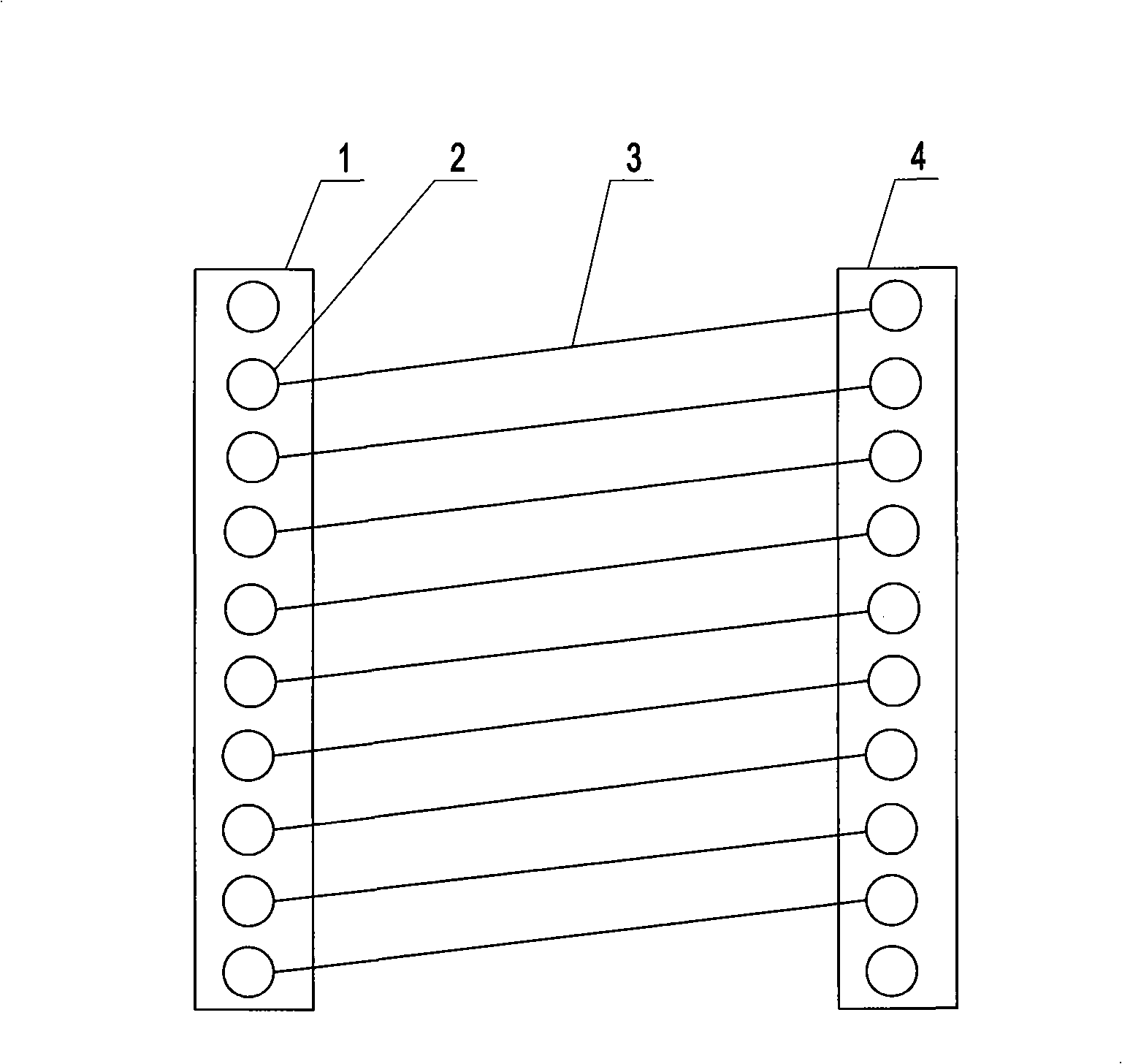
[0009] Such as figure 1 Shown is a winding tool for testing the excitation characteristics of a current transformer coil, which includes two insulating plates 1 and a plurality of wires 3, one insulating plate 1 is evenly fixed with a plurality of copper buttons 2, and the other insulating plate 1 A plurality of copper buckle females 4 are evenly fixed on the top, and the copper buckle male 2 corresponds to the copper buckle female 4 one by one. One end of the wire 3 is fixed on a copper buckle male 2, and the other end is fixed on a wire diagonally opposite to the aforementioned copper buckle male 2. After the copper buckle female 4 and the copper buckle male 2 on the two insulation boards 1 are fastened together, a plurality of wires 3 are connected end to end in turn to form a helical coil.
[0010] Test method: during the test, the tooling can be directly wound on the iron core, and then the two insulating plates 1 are pressed tightly, the copper buckle female 4 and the co...
PUM
 Abstract
Description
Claims
Application Information