
Phase changing method and apparatus of 3 phase salient brushless DC motor

A DC motor and DC current technology, applied in the direction of electronic commutator, etc., can solve the problems of poor reliability of rotor pre-positioning, uncertain initial position, complicated circuit debugging, etc., and achieve the elimination of positioning dead zone, high reliability, and detection method reliable effect

Inactive Publication Date: 2009-01-07
BEIJING INST OF AEROSPACE CONTROL DEVICES
View PDF0 Cites 15 Cited by
  • Summary
  • Abstract
  • Description
  • Claims
  • Application Information

AI Technical Summary

Problems solved by technology

The disadvantages of this starting method are: First, the reliability of rotor pre-positioning is poor, that is, when the north pole of the rotor is in the opposite direction to the direction of the applied electromagnetic force, the torque acting on the rotor is close to zero at this time, making the initial position uncertain ;Secondly, the portability is poor, that is, the timing of the applied voltage or current needs to be readjusted for different motors and different load conditions; finally, the circuit debugging is complicated, that is, the timing of the applied voltage or current of the motor needs repeated trial and error to achieve the predetermined Effect

Method used


Image

  • Phase changing method and apparatus of 3 phase salient brushless DC motor
  • Phase changing method and apparatus of 3 phase salient brushless DC motor
  • Phase changing method and apparatus of 3 phase salient brushless DC motor

Examples


Embodiment Construction

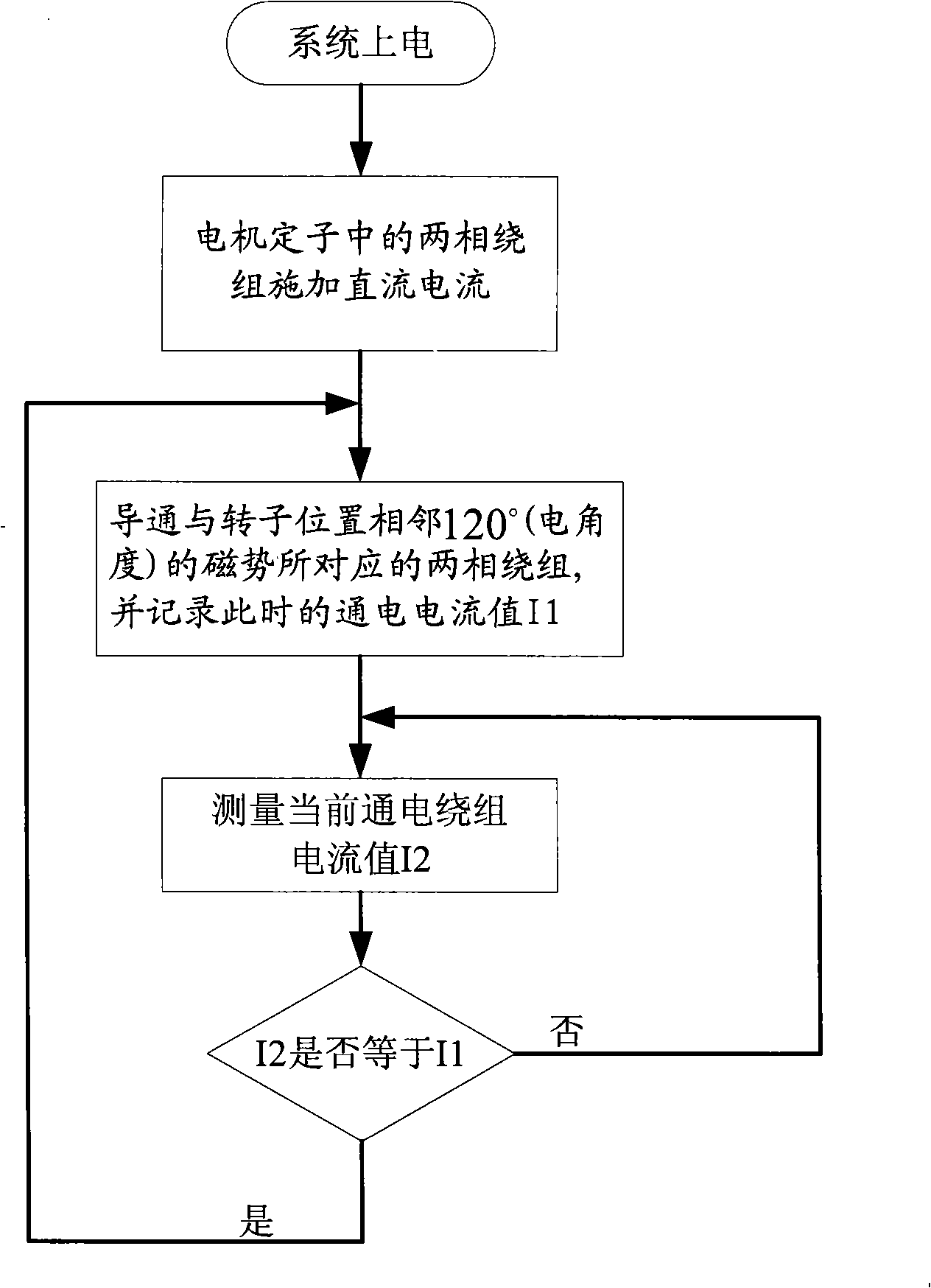
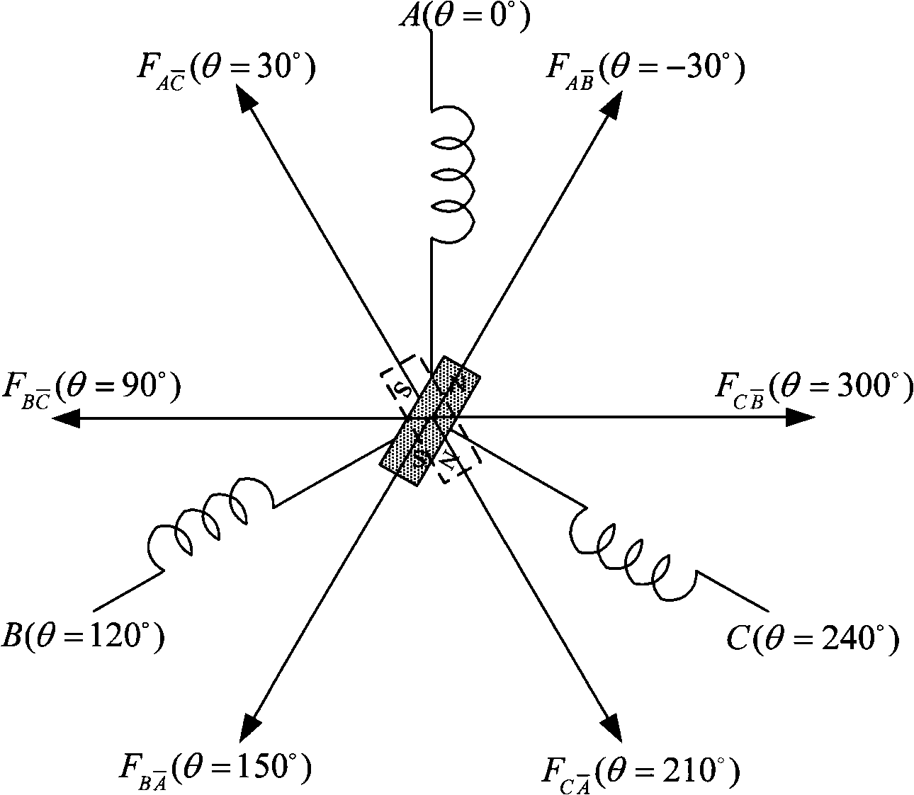
[0042] Such as figure 1 Shown is the flow chart of the commutation method of the present invention. First, direct current is applied to two of the three-phase windings of the three-phase salient-pole brushless DC motor, so that the stator winding generates a positioning magnetic potential, and the rotor is dragged into a certain position. Predicted initial position. Then, according to the initial position of the rotor and the target rotation direction, power is applied to the two-phase winding corresponding to the magnetic potential 120° ahead of the initial position of the rotor, and the initial value I1 of the energized current at this time is recorded. Then detect the change of the current value I2 of the stator two-phase winding that is currently powered on. When the current value I2 in the winding is equal to the initial value I1 of the current, the stator winding is commutated. At this time, the electric angle is 120° ahead of the current position of the rotor Accordin...


PUM


Abstract

The invention relates to a phase changing method of a three-phase salient pole brushless direct current motor, the phase changing method firstly imposes direct current on a two-phase winding in a motor stator, thereby leading the winding of the stator to generate a positioning magnetic potential and dragging a rotor to enter a certain predicted initial position. The two-phase winding which is corresponding to the magnetic potential that is ahead of the initial position of the rotor by an electrical angle of 120 degrees is conducted along the target rotation direction, when current flow achieves the initial value of the current flow of the current two-phase winding, the two-phase winding which is corresponding to the magnetic potential that is ahead of the current position of the rotor by the electrical angle of 120 degrees is conducted, and the two-phase winding which is corresponding to the magnetic potential that is ahead of the position of the rotor at the phase changing point by the electrical angle of 120 degrees is gradually conducted according to the phase changing method, thereby pushing the rotor to rotate to the target direction. The invention discloses a realization device according to the method. The phase changing method can accurately detect the phase changing point of the position of the rotor, thereby having the advantages of strong portability, simple realization and reliable performance, etc.

Description

technical field [0001] The invention relates to a phase commutation method and a phase commutation device of a motor, in particular to a phase commutation method and a corresponding phase commutation device of a three-phase salient pole brushless DC motor without a position sensor. Background technique [0002] To achieve power-on control of a BLDC motor, the motor voltage or motor current is electronically commutated at certain specific positions on the rotor. In the two-two energization mode of the three-phase brushless DC motor, one power switch tube is turned off every 120 degrees of electrical angle and switched to the next power switch tube. In order to ensure that this commutation process is performed at a predetermined position Phase, the current position of the motor must be known. For such a control method, a special rotor position sensor such as a Hall sensor is usually used to detect the position of the motor or an open-loop starting technology is used to achieve...

Claims


Application Information

Patent Timeline
IPC IPC(8): H02P6/18
Inventor 翟波李建春王晓瑜
Owner BEIJING INST OF AEROSPACE CONTROL DEVICES
Learn More