Transfer plate and method for loading a cargo space

A transfer board and cargo location technology, applied in the transfer board field, can solve problems such as automation and inability to load materials

Active Publication Date: 2009-01-07
ACTIW
View PDF1 Cites 14 Cited by
  • Summary
  • Abstract
  • Description
  • Claims
  • Application Information

AI Technical Summary

Problems solved by technology

Loading cannot be automated when auxil...

Method used


Image

  • Transfer plate and method for loading a cargo space
  • Transfer plate and method for loading a cargo space
  • Transfer plate and method for loading a cargo space

Examples


Embodiment Construction

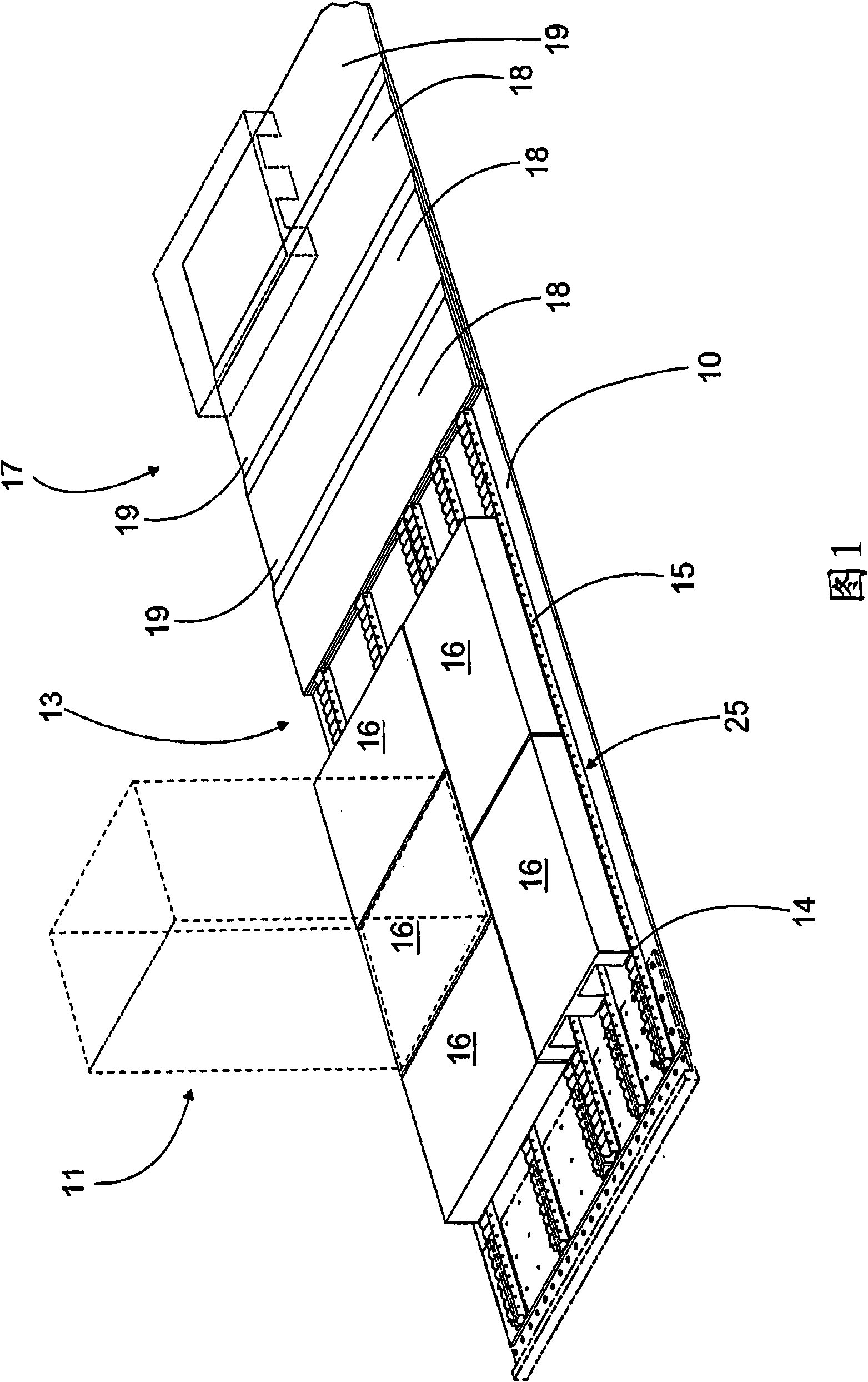
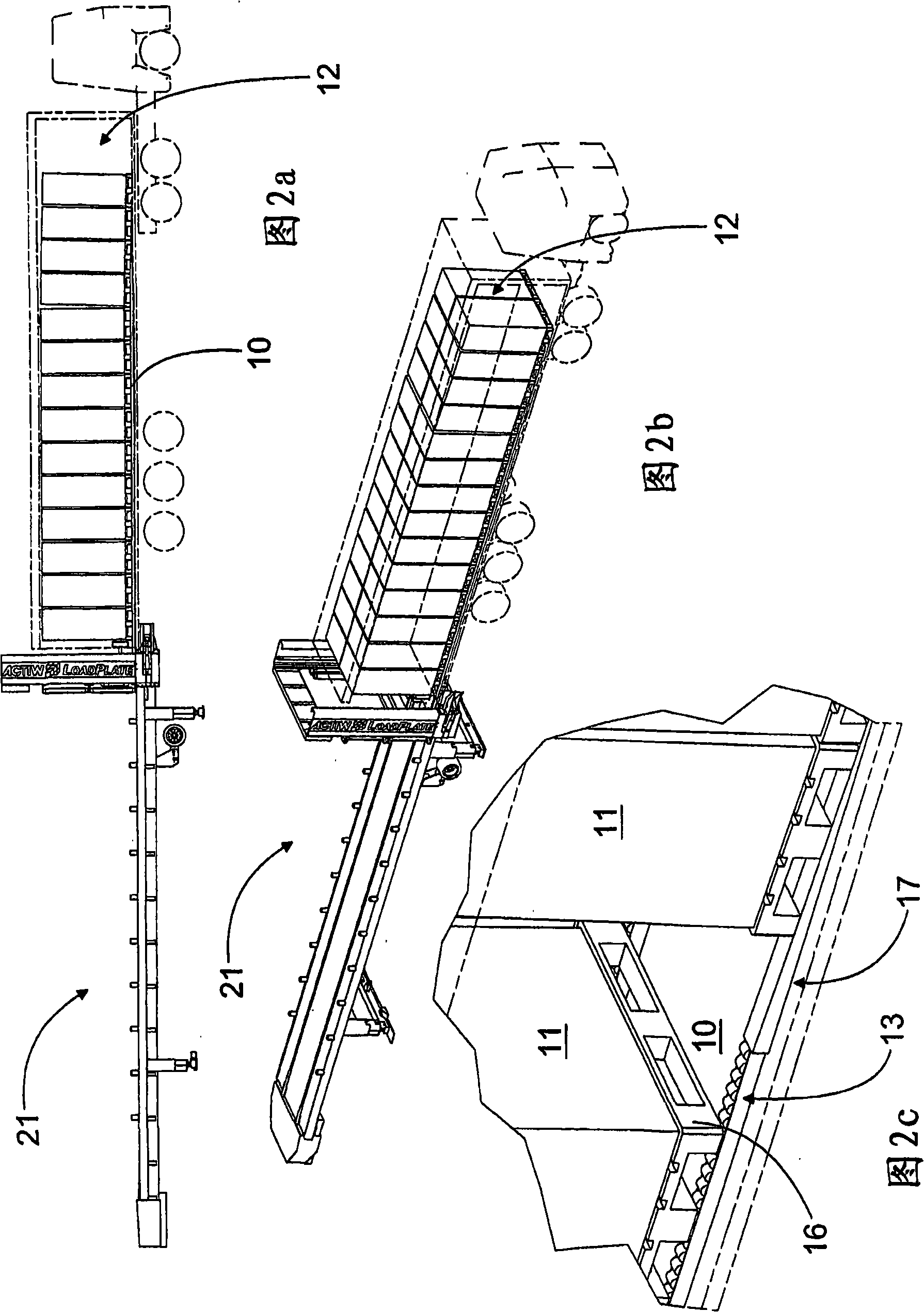
[0014] Figure 1 shows a conveyor plate 10 according to the invention, which is used when loading a storage space. The transfer plate 10 is intended to be transferred with the cargo units 11 to the storage space 12 and moves backwards while leaving the cargo units 11 in the storage space 12 (Figs. 2a and 2b). According to the invention, rolling elements 13 are mounted on the conveyor plate 10 on its surface facing the cargo unit 11 over part of its length so as to be movable between the conveyor plate 10 and the cargo unit 11 . The build-up of loads is thus facilitated and the stresses acting on the cargo unit and the transfer plate are apparently reduced from what is known. The stresses in the cargo unit and the remainder of the equipment are also reduced from those present.

[0015] The configuration, size and total number of rolling elements may vary in different applications. In the application shown, the rolling elements 13 are freely rotating rollers 14 by which the rol...


PUM

PropertyMeasurementUnit
Thicknessaaaaaaaaaa
Thicknessaaaaaaaaaa
Lengthaaaaaaaaaa

Abstract

The invention relates to a transfer plate for loading a cargo space. The transfer plate (10) is intended to be moved, together with cargo units (11), into the cargo space (12) and back again, the cargo units (11) remaining in the cargo space (12). Rolling elements (13) are arranged, over at least a part of the length of the transfer plate (10), on the side of it facing the cargo units (11) to permit movement between the transfer plate (10) and the cargo units (11). The transfer plate (10) is mainly of plastic and the thickness of the structure formed by the transfer plate (10) and the rolling elements (13) is less than 70 millimetres. The invention also relates to a method for loading a cargo space.

Description

technical field [0001] The invention relates to a conveyor plate for loading a cargo space, said conveyor plate being intended to be moved into the cargo space with cargo units and then retracted, while the cargo units remain in the cargo space, with rolling elements mounted over at least part of the length of the conveyor plate , on the side facing the cargo unit so as to be able to move between the transfer plate and the cargo unit. The invention also relates to a method of loading a storage space. Background technique [0002] WO Application Publication No. 9523105 discloses a method and apparatus for loading products to be conveyed into a storage space. The disclosed apparatus utilizes a transfer plate on top of which the load is first formed. Next, the load is pushed into the bay with the transfer plate, after which the transfer plate is pulled out from under the load. The load is supported during pulling of the transfer plate. In the method described above, the pro...

Claims


Application Information

Patent Timeline
IPC IPC(8): B65G67/04
Inventor J·考哈宁
Owner ACTIW
Why Eureka
Try Eureka