Supercharge Your Innovation With Domain-Expert AI Agents!

Multi-link lever suspension fork regulating mechanism

An adjustment mechanism, multi-link technology, applied in the direction of axle suspension, bicycle accessories, transportation and packaging, etc., can solve the problems of increasing danger, affecting driving feeling, stress concentration, etc., and achieving the effect of high reliability and simple structure

Active Publication Date: 2009-01-14
YAMAHA MOTOR CO LTD
View PDF0 Cites 2 Cited by
  • Summary
  • Abstract
  • Description
  • Claims
  • Application Information

AI Technical Summary

Problems solved by technology

[0006] But, when changing the length of two connecting rods 50a, two connecting rods 50a must be pulled down from the vehicle frame 10a, first loosen the fixing nut 51a, and then turn the upper and lower parts of the connecting rods 50a to the required length Finally, the fixing nut 51a is finally tightened and fixed. In this way, there are many components that need to be disassembled during adjustment, and it is easy to cause inconsistent adjustments of the left and right linkage rods 50a, resulting in stress concentration problems. When the moving rod 50a has a structure to adjust the length, the connecting rod 50a is likely to loosen or break, and even the thread collapses. In this way, not only can it not be adjusted by electric means, but it will also increase the risk
[0007] In addition, another existing multi-link suspension mechanism adds a length adjustment mechanism (not shown in the figure) to the shock absorber unit, by adjusting the length of the shock absorber to drive other related components to rotate, thereby adjusting the height of the vehicle body, However, this method will cause the price of the shock absorber unit to be too high, making it difficult to introduce mass-produced cars, and also cannot be adjusted electrically. In addition, this method will greatly change the action angle of the shock absorber when adjusting the height of the vehicle, so Affects the feeling of driving

Method used


Image

  • Multi-link lever suspension fork regulating mechanism
  • Multi-link lever suspension fork regulating mechanism
  • Multi-link lever suspension fork regulating mechanism

Examples


Embodiment Construction

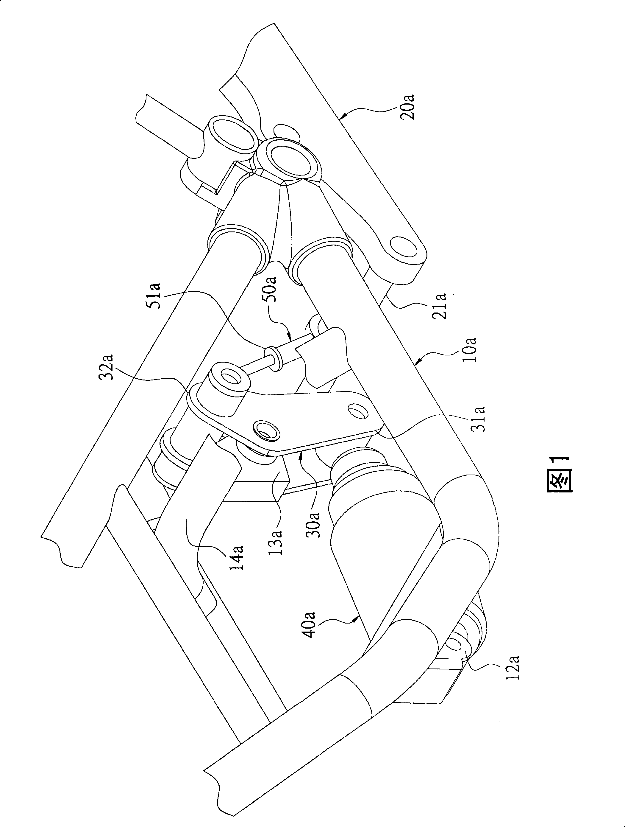
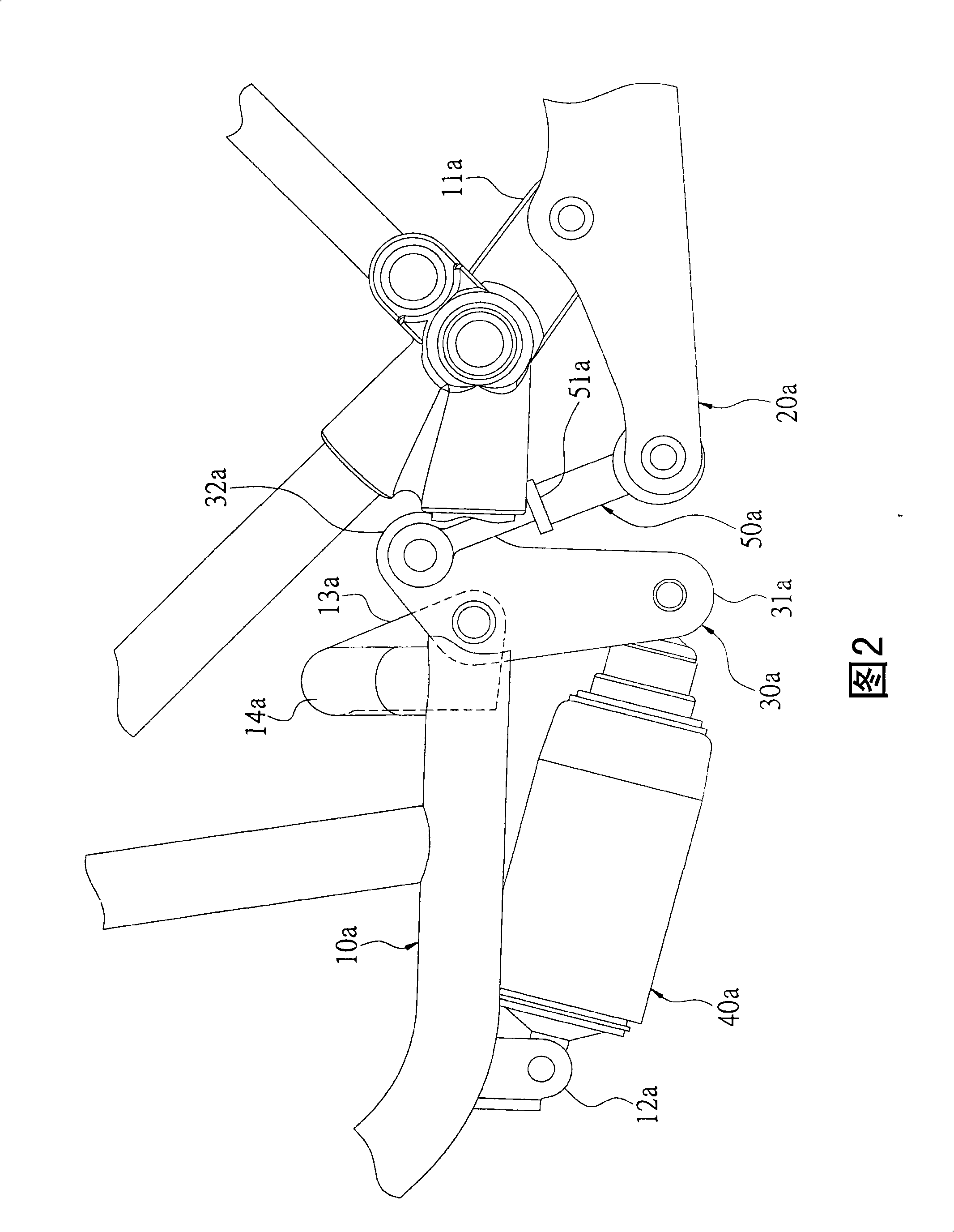
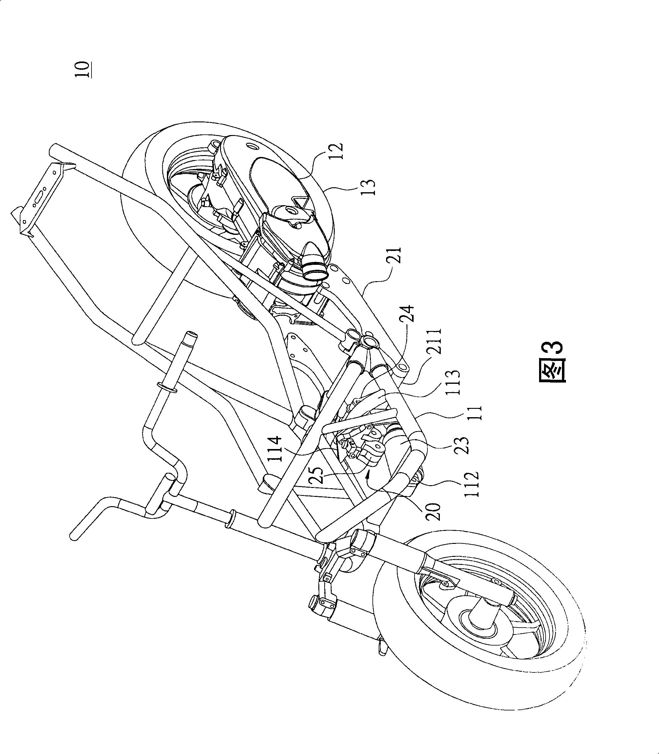
[0023] Please refer to Figures 3 to 6, which show the first embodiment of the present invention. This embodiment takes a two-wheeled vehicle 10 as an example for description, but the present invention is not limited to being applied to the two-wheeled vehicle 10. It can be other types of vehicles, such as scooter vehicles, gear-shifting vehicles, and power vehicles, among which the power vehicles are all-round off-road vehicles (ATV), golf carts, and snow-mobile vehicles.

[0024] The motorcycle 10 has a frame 11 and a power unit 12, wherein the rear end of the frame 11 is provided with a first pivot seat 111 (as shown in FIG. 5) on opposite sides of the rear end, and a second pivot seat is provided at the front end. 112. The second pivot seat 112 is separated from the two first pivot seats 111 at a distance. The bottom of the frame 11 is provided with a transverse bracket 113. The transverse bracket 113 is connected with a triangular fixing piece 114. The rear side of the fixing ...


PUM


Abstract

A suspension bracket adjusting mechanism with multiple connecting rods is connected between a vehicle frame and a power unit. The suspension bracket adjusting mechanism with multiple connecting rods comprises two frames, a bearing connecting rod, an antivibrator, two linkage rods and an adjusting device. The two frames are connected to a power unit and a shaft lever is arranged between the two frames; the bearing connecting rod is provided with a first end and a second end; one end of the antovibrator is pivoted at the front end of the vehicle frame and the other end is pivoted at the first end of the bearing connecting rod; one end of each linkage rod is pivoted to the shaft lever and the other end is pivoted to the second end of the bearing connecting rod; the adjusting device is arranged at one side of the bearing connecting rod. In this way, the height of the vehicle can be adjusted by only changing the position of the bearing connecting rod.

Description

Technical field [0001] The present invention relates to a multi-link suspension adjustment mechanism, which is used to install two-wheeled vehicles or other types of wheeled vehicles, such as scooter vehicles, gear-shifting vehicles, and power vehicles (that is, all-round off-road vehicles ( ATV), golf carts and snowmobiles, etc.), in particular to a multi-link suspension adjustment mechanism that can be used to adjust the height of the vehicle. Background technique [0002] Please refer to Figure 1 and Figure 2, the existing multi-link suspension mechanism is connected to the frame 10a, the frame 10a is provided with two first pivot seats 11a (shown in Figure 2) and a second For the pivot seat 12a, a transverse bracket 14a extends transversely from the bottom end of the frame 10a, and the transverse bracket 14a integrally extends to form a third pivot seat 13a. [0003] The above-mentioned multi-link suspension mechanism includes: two engine hangers 20a, a load-bearing link 30a,...

Claims


Application Information

Patent Timeline
Patent Type & Authority Applications(China)
IPC IPC(8): B62K25/26
Inventor 洪瑞达
Owner YAMAHA MOTOR CO LTD
Features
  • R&D
  • Intellectual Property
  • Life Sciences
  • Materials
  • Tech Scout
  • Unparalleled Data Quality
  • Higher Quality Content
  • 60% Fewer Hallucinations
Learn More