Laser amplifying measurement method for bending structure deformation

A technology of laser amplification and bending and torsion structure, which is applied in the direction of measuring devices, optical devices, instruments, etc., can solve the problems of insufficient accuracy, large measurement error, inconvenience, etc., and achieve the effect of avoiding insufficient accuracy

Inactive Publication Date: 2009-01-14
YANGZHOU UNIV
View PDF0 Cites 43 Cited by
  • Summary
  • Abstract
  • Description
  • Claims
  • Application Information

AI Technical Summary

Problems solved by technology

For example, to measure the change of bridge stiffness, it is often necessary to measure the deflection or rotation angle of the bridge. For this reason, scaffolding has to be set up in the water under the bridge to install related contact measuring instruments. This method is obviously very inconvenient and the effect is not ideal.
Non-contact measuring instruments have always had the problem of insufficient accuracy in the long-distance measurement of small deformations of large structures. The reason is that the current non-contact measurement method is to track the measuring instrument When the displacement of the measuring point is perpendicular to the line connecting the instrument and the measuring point, the measuring principle is actually a method of measuring the angle
When the displacement of the measurement point is very small, the change of the measurement angle is very small, so the measurement error is too large to be widely used

Method used


Image

  • Laser amplifying measurement method for bending structure deformation
  • Laser amplifying measurement method for bending structure deformation
  • Laser amplifying measurement method for bending structure deformation

Examples


Embodiment Construction

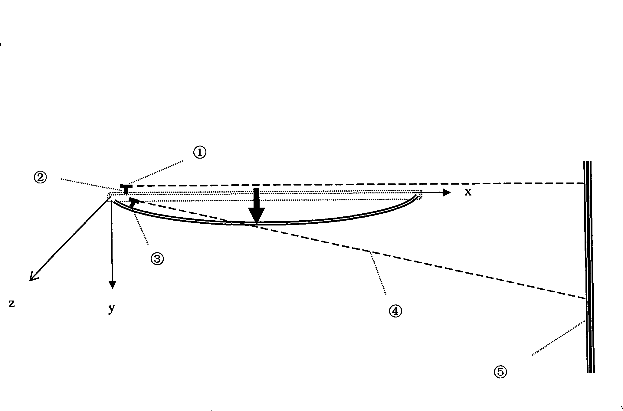
[0018] Such as figure 1 Shown:

[0019] First, according to the deformation characteristics of the specific bending and torsion structure or member to be measured, determine the measurement position of the bending and torsion member to be tested. The principle of general measurement point selection is to select the bending and torsion member to be tested to have the largest absolute rotation (rotation angle or torsion angle) as much as possible. parts. Then place the laser beam emitter together with the bracket on the point to be measured of the bending and torsion structure (object) to be measured, and rely on manual or mechanical aiming to align the beam with the pre-set light target reference position in the distance. When the load acts on the structure to be measured, the corresponding rotation (rotation angle or torsion angle) will occur at the measuring point. This turning or twisting angle will be magnified by the laser beam to a distant light target. By reading the ...


PUM


Abstract

The invention relates to a laser amplification measurement method of the deformation of a twisted structure by utilizing laser. The technical proposal of the invention is as follows: a support is arranged on a rotation angle part to be measured of the twisted structure to be measured, a laser beam transmitter is arranged on the support, a scale optical target is set, when the twisted structure to be measured is displaced or twisted, a laser beam which is transmitted by the laser beam transmitter is displaced at a projection point on the optical target, a deformation valve of the rotation angle or a twist angle of a measurement point of the twisted structure to be measured is obtained according to the formula that Theta is equal to arctg (Delta divided by L), and the stiffness parameters of the twisted structure to be measured is calculated, thereby obtaining the tiny rotation deformation amount of the point to be measured. The shortcoming that the non-contact measurement instruments are always lack of precision on the long-distance measurement of the tiny deformation of large-scale structures is solved. The laser amplification measurement method of the invention arranges the measurement instrument on a measured object to allow the measurement instrument to move together with the deformed part of the measured object, thereby having the advantage that the tiny displacement to be measured is fully amplified by utilizing the optical lever principle.

Description

technical field [0001] The invention relates to the accurate measurement of micro-bending or torsion deformation of structures, in particular to a laser amplification measurement method for bending and torsion structure deformation by using laser. Background technique [0002] Prior to the present invention, an absolute reference object was often required for small deformation measurements of structures subjected to bending or torsion. For example, to measure the change of bridge stiffness, it is often necessary to measure the deflection or rotation angle of the bridge. For this reason, scaffolding has to be set up in the water under the bridge to install related contact measuring instruments. This method is obviously very inconvenient and the effect is not ideal. . Non-contact measuring instruments have always had the problem of insufficient accuracy in the long-distance measurement of small deformations of large structures. The reason is that the current non-contact measu...

Claims


Application Information

Patent Timeline
Patent Type & Authority Applications(China)
IPC IPC(8): G01B11/16
Inventor 刘平
Owner YANGZHOU UNIV
Why Eureka
Try Eureka