

Water meter electromagnetic flowmeter
A technology of electromagnetic flowmeter and water meter, which is applied in the application of electromagnetic flowmeter to detect fluid flow, volume/mass flow generated by electromagnetic effect, volume measurement, etc. Reversing and other problems, to achieve the effect of facilitating network management, improving work reliability, and overcoming malfunctions
Inactive Publication Date: 2009-01-14
TIANJIN JINNAN KAIDA ELECTRONIC CO LTD
View PDF0 Cites 6 Cited by
- Summary
- Abstract
- Description
- Claims
- Application Information
AI Technical Summary
Problems solved by technology
[0002] The existing water meter pulse signal device can only measure the flow through the water meter in the normal water flow direction, but cannot detect and measure the water theft phenomenon when the water meter is inverted. At present, the wet water meter pulse signal device cannot determine whether the magnetic pointer is forward or reverse. , so the phenomenon of stealing water when the water meter is inverted cannot be found in time, and when the magnetic pointer and the magnetic sensitive element are in a critical position, due to the vibration of the magnetic pointer, there will be misoperation, and the work reliability is poor.
Method used
View moreImage
Smart ImageViewing Examples

Examples
Embodiment
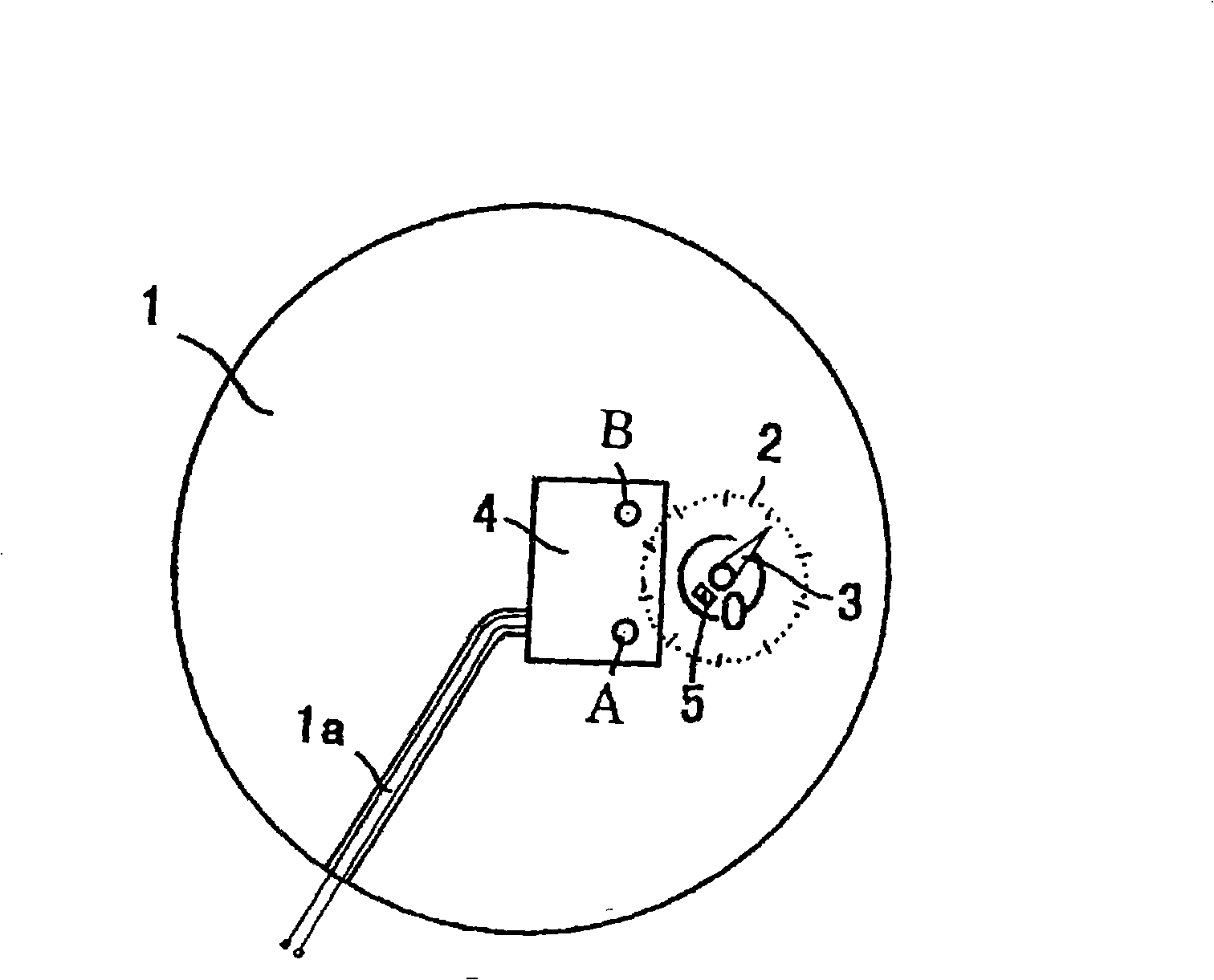
[0007] Embodiment: An electromagnetic flowmeter for a water meter. A circuit board 4 and reed switches A and B are installed on the inner cover 1 of the rotor-type water meter. The axis of the 0.01 ton magnetic pointer 3 is set to 0, and the pulse signal transmission line is arranged in the groove. In 1a, according to the timing difference of the output pulse signal, determine whether the magnetic pointer is forward or reverse, that is, whether the water meter is installed in a forward or backward direction, and whether water theft occurs.
Login to View More PUM
 Abstract
The invention discloses an electromagnetic flow meter of a water gauge, which has the following structure: a circuit board and a reed switch are arranged on a rotor inner cap of the water gauge, pulse signal transmission lines are arranged in a groove, either a magnetic indicating hand rotates positively or reversely is determined according to the sequential difference between output pulse signals, and either the water gauge is arranged positively or reversely is determined, thus deciding whether water stealing phenomenon happens. The electromagnetic flow meter of the water gauge has the following advantages: the electromagnetic flow meter overcomes the malfunctions generated by the wobble of the magnetic indicating hand, raises functional reliability, and is favorable for realizing network management.
Description
technical field [0001] The invention relates to a water meter electromagnetic flowmeter. Background technique [0002] The existing water meter pulse signal device can only measure the flow through the water meter in the normal water flow direction, but cannot detect and measure the water stealing phenomenon when the water meter is inverted. At present, the wet water meter pulse signal device cannot determine whether the magnetic pointer is forward or reverse. , so the phenomenon of stealing water when the water meter is inverted cannot be found in time, and when the magnetic pointer and the magnetic sensitive element are in a critical position, due to the vibration of the magnetic pointer, malfunctions will occur, and the work reliability is poor. Contents of the invention [0003] The object of the present invention is to overcome the above-mentioned defects and provide a water meter electromagnetic flowmeter. [0004] The technical solution of the present invention is:...
Claims
Login to View More Application Information
Patent Timeline
 IPC IPC(8): G01F1/58G01F15/00
Inventor崔连凯
OwnerTIANJIN JINNAN KAIDA ELECTRONIC CO LTD