Scanning synthetic pore diameter laser imaging radar

A technology of synthetic aperture laser and imaging radar, which is applied in the direction of instruments, measuring devices, using re-radiation, etc.

Inactive Publication Date: 2009-01-14
SHANGHAI INST OF OPTICS & FINE MECHANICS CHINESE ACAD OF SCI
View PDF0 Cites 10 Cited by
  • Summary
  • Abstract
  • Description
  • Claims
  • Application Information

AI Technical Summary

Problems solved by technology

However, the above-mentioned synthetic aperture lidar imaging radars all require that there must be relative motion between the lidar and the observed object

Method used


Image

  • Scanning synthetic pore diameter laser imaging radar
  • Scanning synthetic pore diameter laser imaging radar
  • Scanning synthetic pore diameter laser imaging radar

Examples


Embodiment Construction

[0075] The present invention will be further described below in conjunction with the accompanying drawings and embodiments, but the protection scope of the present invention should not be limited thereby.

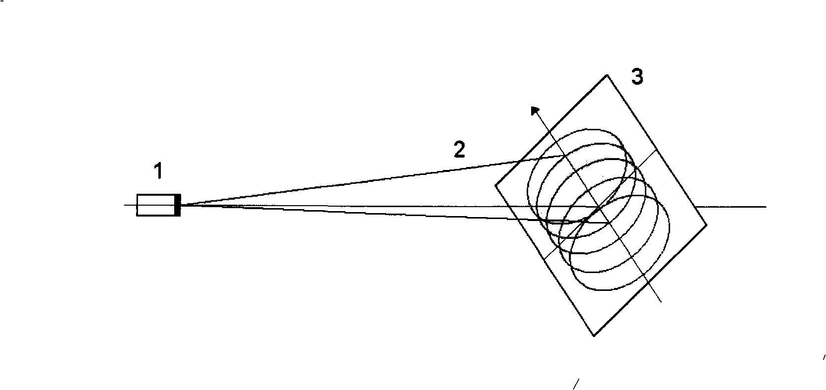
[0076] see first figure 1 , the structure and working method of the scanning synthetic aperture laser imaging radar of the present invention are as follows figure 1 As shown, the laser beam emitted from the imaging synthetic aperture lidar 1 forms an optical footprint 2 on the measured object plane 3 .

[0077] The relative position between the synthetic aperture imaging laser radar 1 and the measured object plane 3 is constant, the measured object plane 3 and the main axis of the synthetic aperture laser imaging radar 1 have a certain angle, and the synthetic aperture laser imaging radar 1 adopts integral device scanning or additional optical The method of deflector scanning scans the optical footprint 2 and realizes linear scanning on the imaging object plane 3 . The op...


PUM


Abstract

A scan laser-imaging SAR is characterized in that the scan laser-imaging SAR comprises a laser-imaging SAR which is composed of an optical emission system and an optical receiving system; the optical receiving system is provided with a mechanism used for eliminating echo wave face aberration and the optical emission system is provided with a phase quadratic-term biasing mechanism controlled by lighting facula; a relative position between the laser imaging SAR and the plane of a measured object is preserved and a certain angle between the plane of the measured object and a principal axis of the laser imaging SAR is preserved; an emission signal beam and a heterodyne receiving FOV are concentric and the divergency of the beam is equal to the angle of the heterodyne receiving FOV; the laser-imaging SAR adopts a manner of integrated-apparatus scanning or an additional optical deflector scanning to scan an optical track and can realize the straight-line scanning to the plane of the measured object. The invention can be applied to the to-ground high-resolution imaging by a high-orbit stationary satellite.

Description

technical field [0001] The invention relates to an aperture-forming laser imaging radar, which is a scanning synthetic aperture laser imaging radar. During operation, the laser radar and the observed surface are relatively stationary, and the radar scanning method is adopted for aperture synthesis imaging. The scheme fully utilizes the characteristics of optics, namely The key to easy scanning and controllable phase history generation is to solve the problem of the quadratic item offset of the intrinsic phase generated by radar scanning. The imaging coordinate system is calculated in the radial distance direction and the scanning angle direction. This new type The working mode of scanning synthetic aperture imaging lidar broadens the application range of synthetic aperture imaging lidar, for example, it can be used for high-resolution imaging of high-orbit geostationary satellites. Background technique [0002] Microwave synthetic aperture radar usually has two working modes...

Claims


Application Information

Patent Timeline
Patent Type & Authority Applications(China)
IPC IPC(8): G01S17/89G01S7/481
Inventor 刘立人
Owner SHANGHAI INST OF OPTICS & FINE MECHANICS CHINESE ACAD OF SCI
Why Eureka
Try Eureka