Power transmission device and electronic instrument

A power receiving device and terminal technology, applied in the direction of circuit devices, battery circuit devices, electrical components, etc., can solve problems such as inability to properly control power circuits

Inactive Publication Date: 2009-01-14
SEIKO EPSON CORP
View PDF10 Cites 24 Cited by
  • Summary
  • Abstract
  • Description
  • Claims
  • Application Information

AI Technical Summary

Problems solved by technology

Therefore, in the power transmission device, if the adverse effect caused by the a

Method used


Image

  • Power transmission device and electronic instrument
  • Power transmission device and electronic instrument
  • Power transmission device and electronic instrument

Examples


Embodiment Construction

[0037] Preferred embodiments of the present invention will be described in detail below. In addition, the embodiments described below do not unreasonably limit the content of the present invention described in the protection scope of the present invention, and not all the configurations described in the embodiments are essential technical features of the present invention.

[0038] 1. Electronic equipment

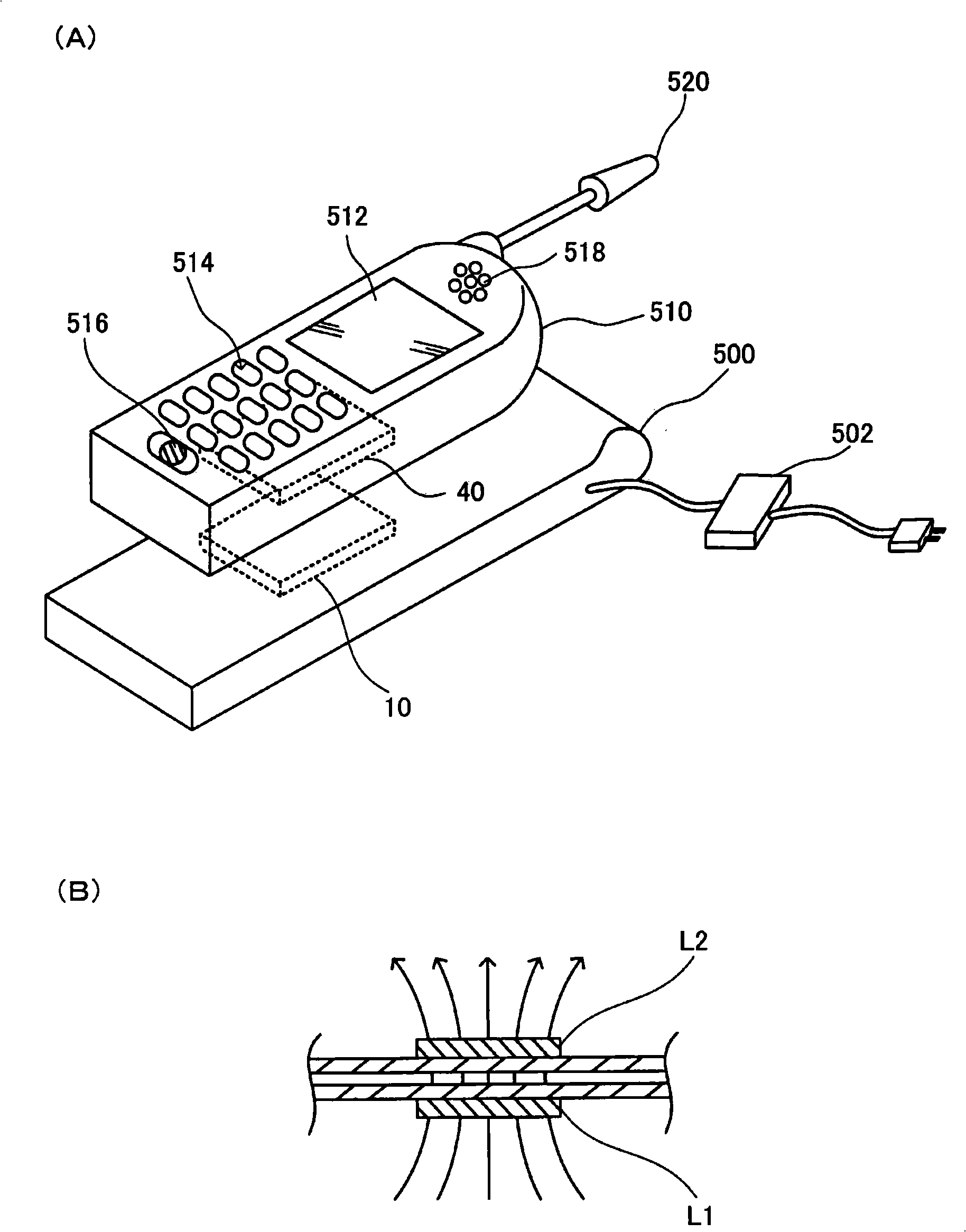
[0039] figure 1(A) shows an example of electronic equipment to which the contactless power transmission method of this embodiment is applied. A charger 500 (cradle, cradle) as one of electronic devices has a power transmission device 10 . Furthermore, a mobile phone 510 as one of electronic devices has a power receiving device 40 . Furthermore, mobile phone 510 includes display unit 512 such as LCD, operation unit 514 including buttons and the like, microphone 516 (voice input unit), speaker 518 (voice output unit), and antenna 520 .

[0040] In charger 500 , electric p...


PUM


Abstract

A power transmission device includes a resonant capacitor that forms a series resonant circuit with a primary coil, a first power transmission driver and a second power transmission driver that drive the primary coil, and a control IC that outputs driver control signals to the first and second power transmission drivers. The resonant capacitor, the first and second power transmission drivers, andthe control IC are provided on a substrate. An output terminal that outputs the driver control signal to the first transmission driver is provided on a first side of the control IC, an output terminal that outputs the driver control signal to the second transmission driver is provided on a second side of the control IC, and an input terminal that receives a signal waveform at one of coil connection terminals through a waveform detection wiring pattern is disposed on a third side of the control IC. The resonant capacitor, the first power transmission driver, and the second power transmission driver are disposed between a first substrate side parallel to the first side of the control IC and the control IC, and the waveform detection wiring pattern extends in an area between a second substrate side and an extension of the third side of the control IC and is connected to one of the coil connection terminals.

Description

technical field [0001] The invention relates to a power transmission device and electronic equipment that transmit power in a non-contact manner. Background technique [0002] In recent years, non-contact power transmission (non-contact power transmission), which can transmit power by electromagnetic induction even if there is no contact between metal parts, has attracted attention. As an application example of this contactless power transmission, charging of a mobile phone, a home electric appliance (for example, a handset of a telephone), and the like have been proposed. [0003] Patent Document 1 exists as a prior art of contactless power transmission. In Patent Document 1, a series resonant circuit is constituted by a resonance capacitor connected to the output of a power transmission driver and a primary coil, and power is supplied from a power transmission device (primary side) to a power reception device (secondary side). [0004] Patent Document 1: Japanese Patent ...

Claims


Application Information

Patent Timeline
IPC IPC(8): H02J17/00
CPCH02J7/0011H02J7/025H02J7/0091H02J7/0034H02J7/007192H02J50/90H02J50/12H02J50/60H02J7/00
Inventor 曾我部治彦大西幸太
Owner SEIKO EPSON CORP
Why Eureka
Try Eureka