Paper feeding type scanner with cleaning mechanism
A technology for cleaning mechanisms and scanners, applied in image communication, electrical components, etc., can solve the problems of wear and tear of scanned manuscripts, unbalanced scanning speed of scanning modules, elongated and deformed images, etc. Simple and effective, guarantees clean and quality results
- Summary
- Abstract
- Description
- Claims
- Application Information
AI Technical Summary
Problems solved by technology
Method used
Image
Examples
Embodiment 1
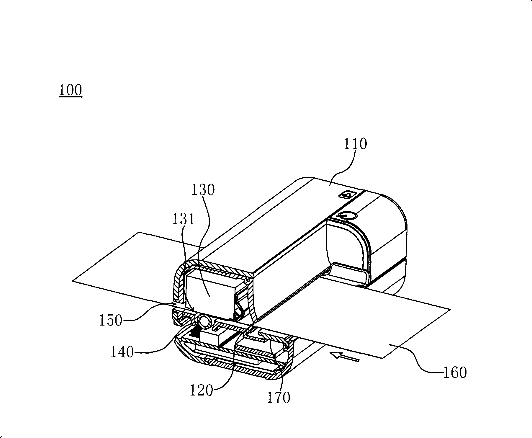
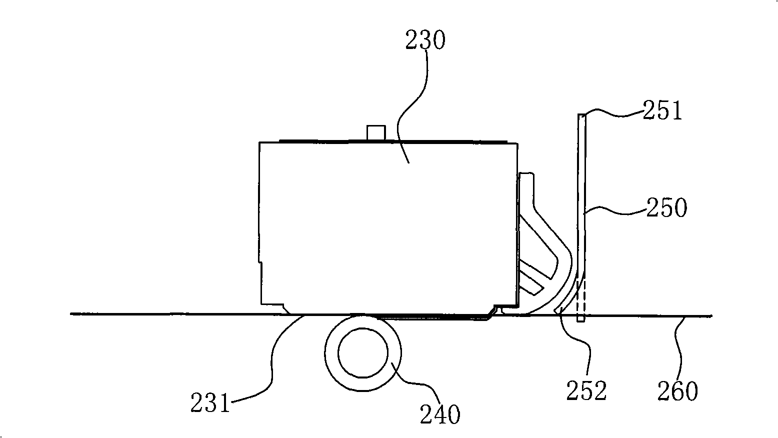
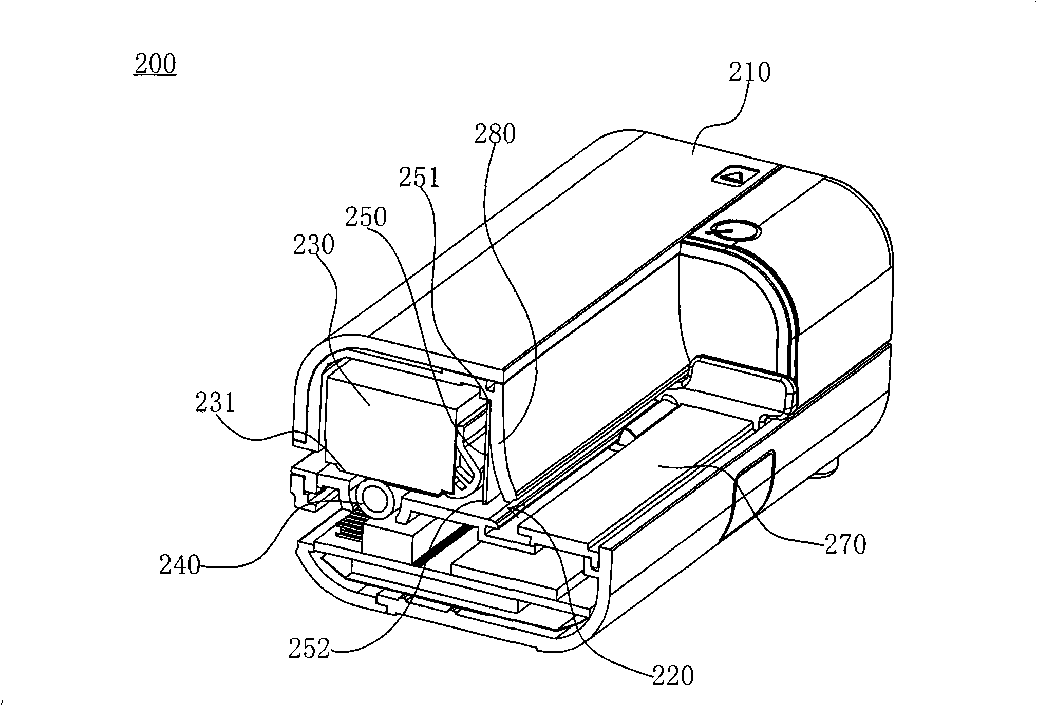
[0033] Embodiment 1 The working principle of the paper-fed scanner with cleaning mechanism is as follows: figure 2 As shown, the CIS scanning module 230 is set statically relative to the body of the paper-fed scanner, and the front end of the scanning module 230 scanning the manuscript 260 is driven by the paper-feeding roller 240, so that the glass window 231 faces the upper end surface of the scanning manuscript 260 Perform linear scanning and obtain scanned images. The cleaning door curtain 250 is erected in the paper feeding direction at the front end of the scanning module 230. The lower end 252 of the cleaning door curtain 250 contacts the scanning end surface of the scanned manuscript 160 to remove dust and other objects attached thereto, thereby Effectively ensure the cleaning performance of the scanning end face, and avoid the occurrence of the attachments adhering to the glass window and affecting the scanning image quality. The upper end 251 of the cleaning door cu...
Embodiment 2
[0037] Example 2 Image 6 A schematic cross-sectional structure diagram of another embodiment of the present invention is shown; the scanner 300 is a miniaturized portable scanner, the CIS scanning module 330 of the scanner 300 is statically arranged relative to the scanner body 310, and the right side of the scanner 300 The side is the paper feeding inlet 320 with the manuscript supporting board 370, and the left side is the paper feeding outlet. The scanned side of the manuscript. On the inner side of the blocking portion 380 above the paper feeding inlet 320 of the scanner, an upright cleaning door curtain 350 is arranged. The cleaning door curtain 350 is an elastic sheet of composite foam material, and its upper end 351 is provided with a dovetail-shaped protrusion, and The inner wall of the scanner housing is provided with a matching dovetail groove, and the dovetail-shaped protrusion of the cleaning curtain 350 is embedded in the dovetail groove, and its lower end 352 i...
Embodiment 3
[0038] Example 3 Figure 7 A schematic cross-sectional structure diagram of Embodiment 3 of the present invention is shown. The scanner 400 is a miniaturized portable scanner. The CIS scanning module 430 of the scanner is statically arranged relative to the scanner body 410. The right side of the scanner 400 is There is a paper feeding inlet 420 with a manuscript supporting board 470, and the left side is a paper feeding outlet. The scanning module 430 is located at the upper left side of the manuscript supporting board 470, and its glass window 431 faces the scanning end face of the scanning manuscripts that enter through the paper feeding inlet 420. . On the inner side of the stopper 480 above the paper feeding inlet 420 of the scanner, there is a cleaning door curtain 450 with an inclined angle. The cleaning door curtain 450 is a flexible sheet, and it is about 160 degrees to the feeding direction of the scanned manuscript. The obtuse angle is set, and its lower end 452 ca...
PUM
 Abstract
Description
Claims
Application Information
 - R&D
- Intellectual Property
- Life Sciences
- Materials
- Tech Scout
- Unparalleled Data Quality
- Higher Quality Content
- 60% Fewer Hallucinations
Browse by: Latest US Patents, China's latest patents, Technical Efficacy Thesaurus, Application Domain, Technology Topic, Popular Technical Reports.
© 2025 PatSnap. All rights reserved.Legal|Privacy policy|Modern Slavery Act Transparency Statement|Sitemap|About US| Contact US: help@patsnap.com


