Resorbable anterior cervical plating system with screw retention mechanism

A threaded, externally threaded technology used in the field of bone stabilization or fixation components to solve problems such as fastener displacement or dislodgement, not providing sufficient mechanical strength or retention, and devices not being visible

Inactive Publication Date: 2009-01-14
SYNTHES GMBH
View PDF0 Cites 12 Cited by
  • Summary
  • Abstract
  • Description
  • Claims
  • Application Information

AI Technical Summary

Problems solved by technology

The disadvantage of these non-metallic devices is that they do not provide sufficient mechanical strength or retention, allowing the fastener to become dislodged or dislodged
Further, these devices may not be visible during imaging of the patient (e.g. with x-rays)

Method used


Image

  • Resorbable anterior cervical plating system with screw retention mechanism
  • Resorbable anterior cervical plating system with screw retention mechanism
  • Resorbable anterior cervical plating system with screw retention mechanism

Examples


Embodiment Construction

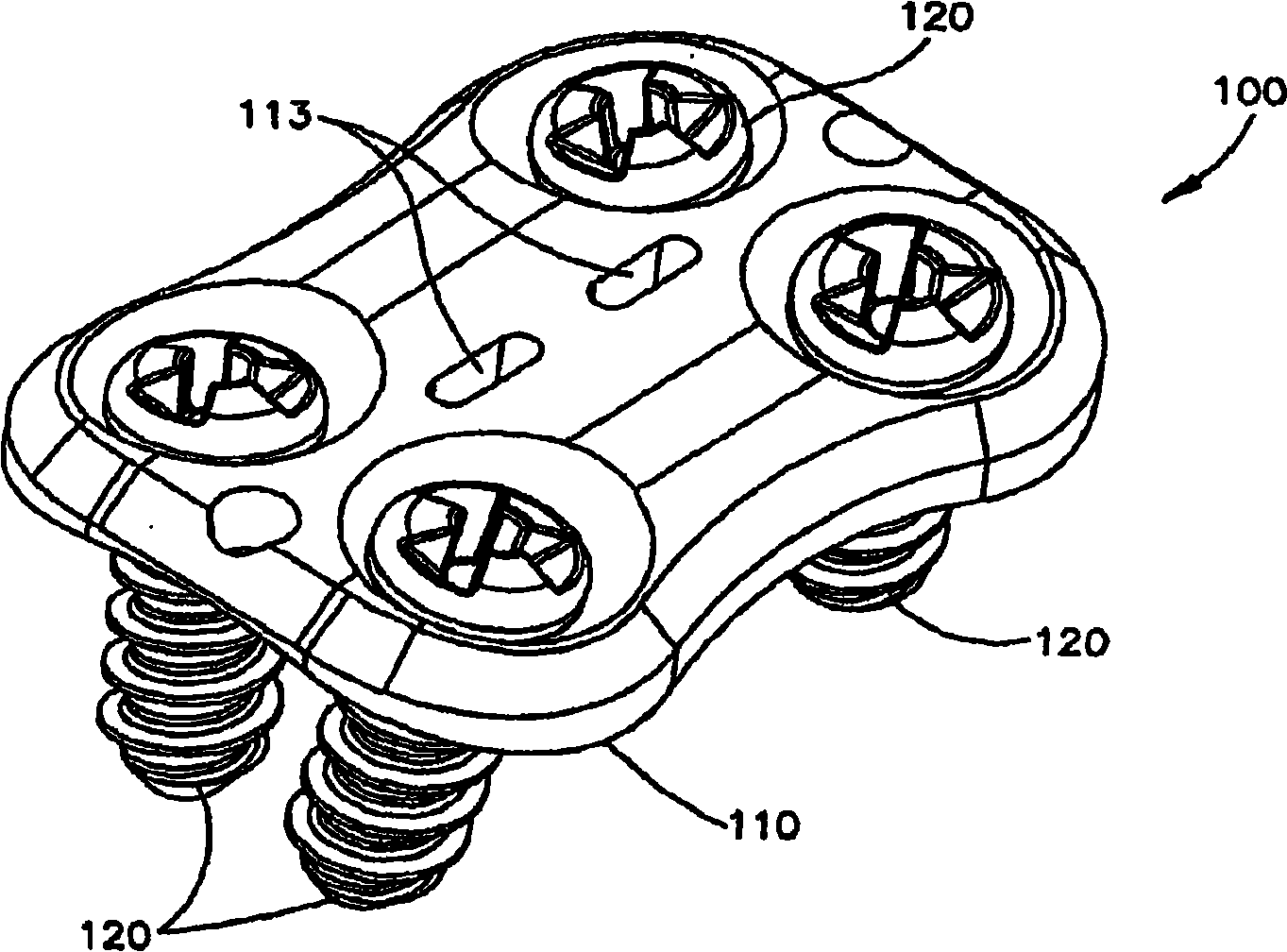
[0034] figure 1 A preferred embodiment of a bone plate assembly 100 (also referred to as a bone fixation assembly or bone stabilization assembly) comprising a bone plate 110 and fasteners 120 is shown in FIG. The bone plate assembly is preferably used in the human spine, preferably in the cervical and / or lumbar region. A bone plate assembly may be attached to, for example, two or more adjacent vertebrae for preventing graft protrusion / extrusion. Provided the bone plates are of suitable strength, the bone plate assembly may also provide stability for aligning and maintaining adjacent vertebrae in a predetermined spatial relationship to one another. Bone plate assemblies may be used in areas other than the spine, such as long bones, for example.

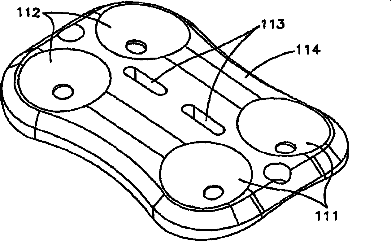
[0035] Bone plate 110 ( Figure 2-6 ) including the upper side 114 ( image 3 ) and the underside or bottom side 115 ( Figure 4 ), while the fixing holes extend from the upper side 114 to the lower side 115. The underside 115 is...


PUM


Abstract

A bone stabilization or fixation assembly may include a bone plate having an upper side and an underside and at least one fixation hole having a first diameter and the hole extending from the upper side to the underside. The area of the bone plate adjacent the fixation hole has a first thickness. The bone stabilization assembly further includes at least one fastener having a head, a shaft, and a relief. The head has a larger dimension than the shaft. The shaft may have threads having a pitch, a core diameter and an outer thread diameter. The relief has a length and a second diameter. The first diameter of the fixation hole may be smaller than the outer thread diameter but larger than the second diameter of the relief. Also, the length of the relief may be greater than the first thickness of the bone plate. The first diameter may be greater than, equal to, or less than the core diameter of the shaft.

Description

[0001] This application claims priority to US Provisional Application No. 60 / 753,372, filed December 21, 2005, which is hereby expressly incorporated by reference in its entirety. technical field [0002] The present invention relates to bone stabilization or fixation assemblies, particularly bone stabilization or fixation assemblies for the spine. Background technique [0003] Orthopedic fixation devices are typically attached to the bone with fasteners such as screws or pins. For example, the bone plate can be secured to the bone with screws inserted through the holes of the plate. In the past, many orthopedic devices were primarily made of metallic materials. Metal fixtures have advantages such as being sterilizable and having the necessary strength for support and fixation. Metal devices, however, have the disadvantage that when repairing a bone defect, the device either remains in the body or is surgically removed. [0004] Recently, improved materials, including non...

Claims


Application Information

Patent Timeline
Patent Type & Authority Applications(China)
IPC IPC(8): A61B17/80A61B17/70A61B17/00A61B19/00A61B17/86
CPCA61B2017/00915A61B17/8052A61B17/7059A61B17/866A61B2017/00004A61B17/8047A61B19/54A61B90/39A61B17/70A61B17/80A61B17/86
Inventor P·伯恩斯D·科赫C·A·罗特
Owner SYNTHES GMBH
Why Eureka
Try Eureka