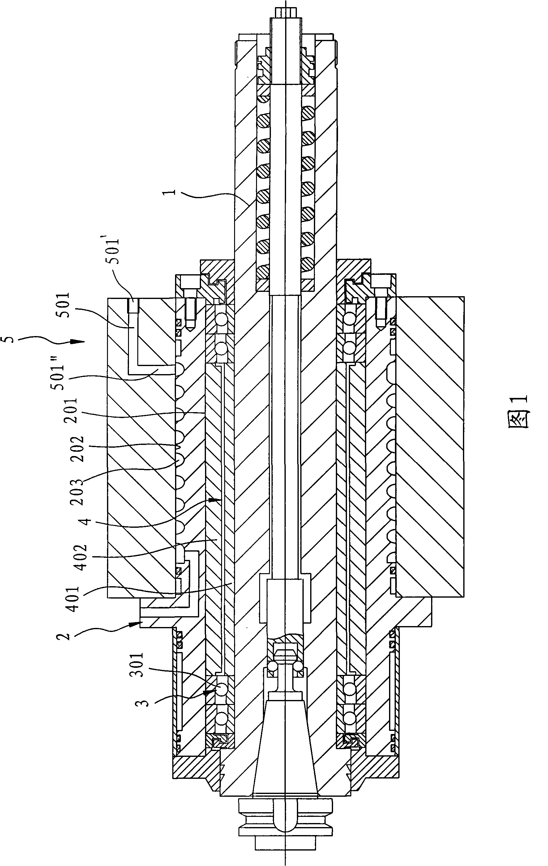
Aircooled type main shaft device of numerically-controlled centre processor
A numerical control, spindle device technology, applied in metal processing machinery parts, manufacturing tools, metal processing equipment, etc., can solve the problems of inability to carry thermal energy away, inconvenience, and poor cooling effect of the spindle device.
- Summary
- Abstract
- Description
- Claims
- Application Information
AI Technical Summary
Problems solved by technology
Method used
Image

Examples
Embodiment Construction
[0019] In order to further explain the technical means and effects of the present invention to achieve the intended purpose of the invention, the specific implementation of the air-cooled spindle device of the numerical control central processing machine proposed according to the present invention will be described below in conjunction with the accompanying drawings and preferred embodiments. , structure, feature and effect thereof, detailed description is as follows.
[0020] The aforementioned and other technical contents, features and effects of the present invention will be clearly presented in the following detailed description of preferred embodiments with reference to the drawings. For convenience of description, in the following embodiments, the same elements are denoted by the same numbers.
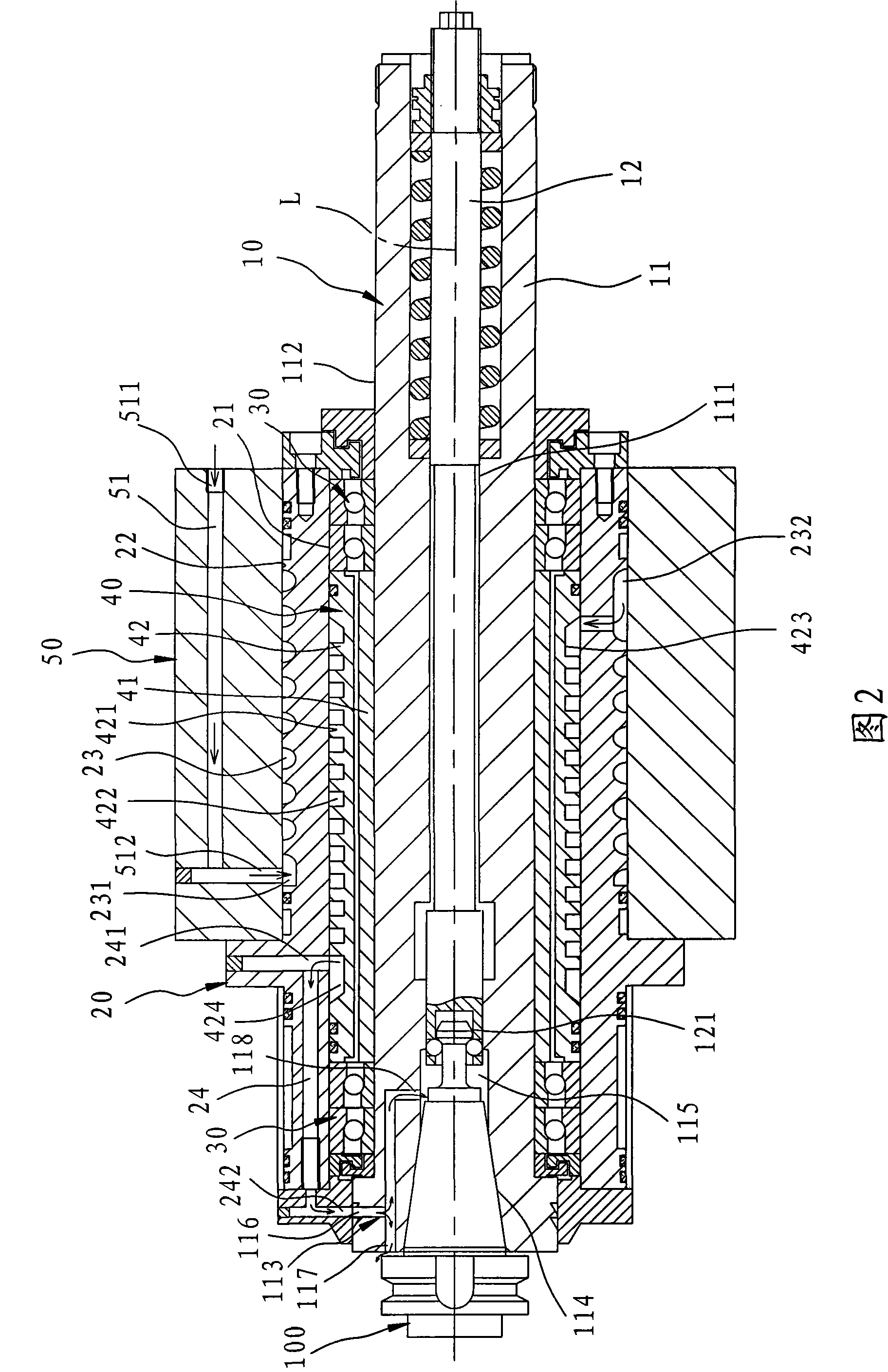
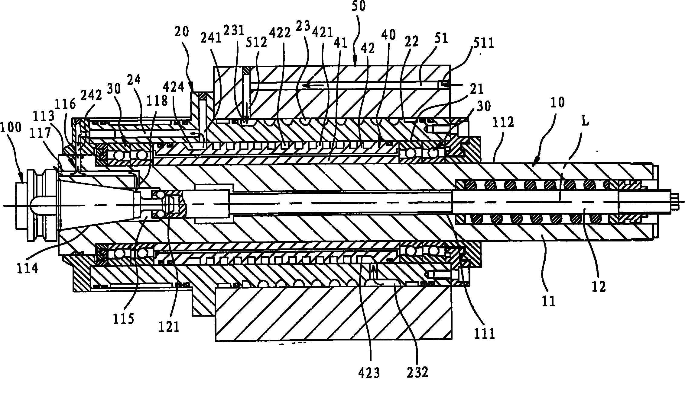
[0021] see figure 2 As shown, it is a schematic cross-sectional view of the combined structure of an embodiment of the air-cooled spindle device of the numerical control center...
PUM
 Abstract
Description
Claims
Application Information