Wing structure having lamellar flow flowing control and separation control

A technology of flow control and separation control, applied in the field of wing structure, can solve problems such as stall, lift drop, separation, etc., to reduce frictional resistance and improve stall characteristics.

Inactive Publication Date: 2009-01-21
BEIHANG UNIV
View PDF0 Cites 50 Cited by
  • Summary
  • Abstract
  • Description
  • Claims
  • Application Information

AI Technical Summary

Problems solved by technology

[0004] In addition, due to the effect of airflow viscosity and the flow direction reverse pressure gradient in the boundary layer, the fluid in the boundary layer will gradually decelerate, and finally the kinetic energy of the fluid in the entire boundary layer is dissipated by the viscous stress, and the fluid can no longer move toward The downstream is flowing, but the upstream boundary layer that has not slowed down is still catching up continuously. The fluid in the boundary layer leaves the upper airfoil because it cannot continue to flow against the upper airfoil, and the flow is separated.
Since the pressure on the leeward side after separation is lower than the pressure at the front of the wing, there is a pressure difference resistance, and the larger the separation area, the greater the pressure difference resistance, and even in the case of severe separation, the lift force will drop sharply, resulting in a stall phenomenon

Method used


Image

  • Wing structure having lamellar flow flowing control and separation control
  • Wing structure having lamellar flow flowing control and separation control
  • Wing structure having lamellar flow flowing control and separation control

Examples


Embodiment Construction

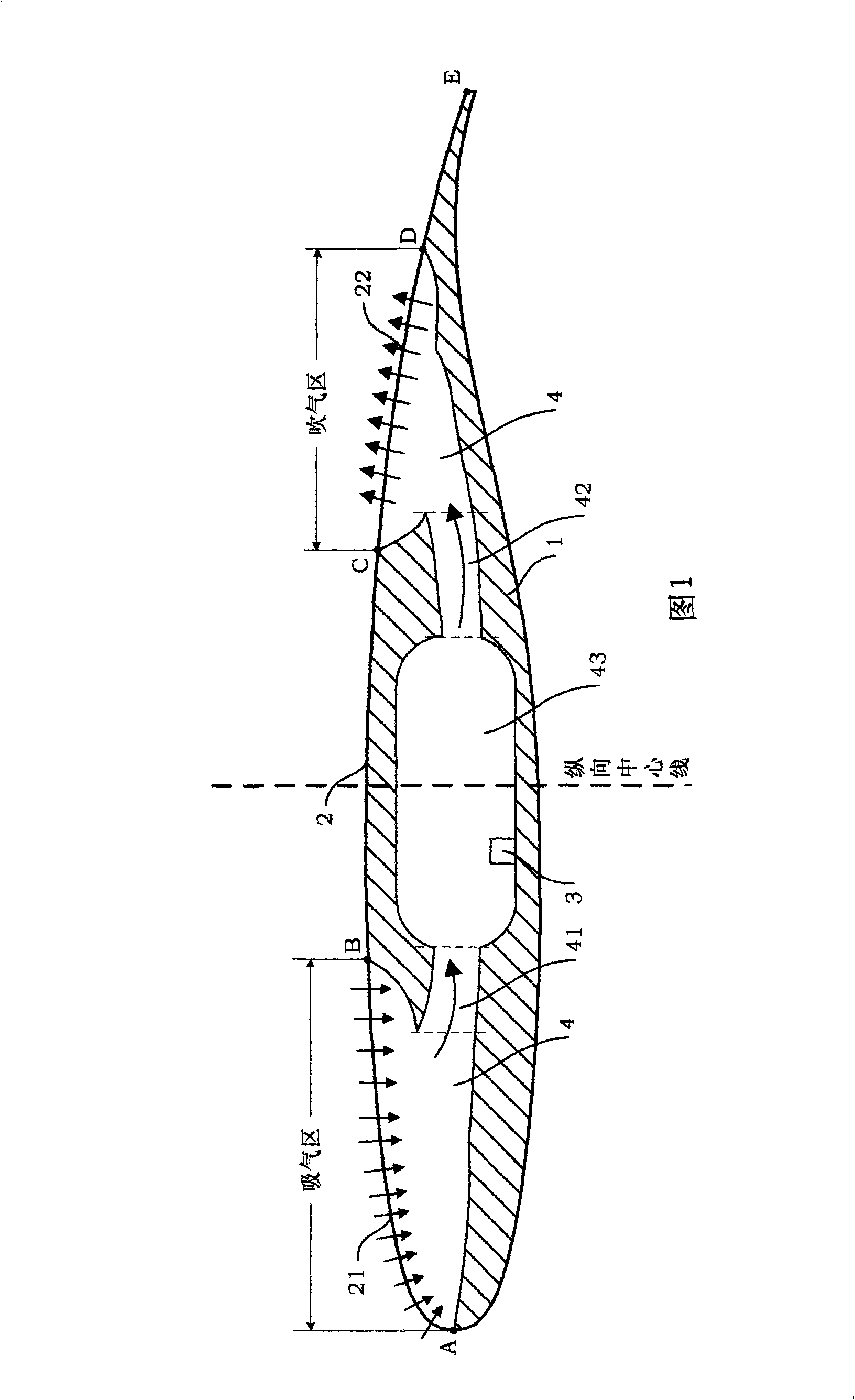
[0028] The present invention will be further described in detail below in conjunction with the accompanying drawings.

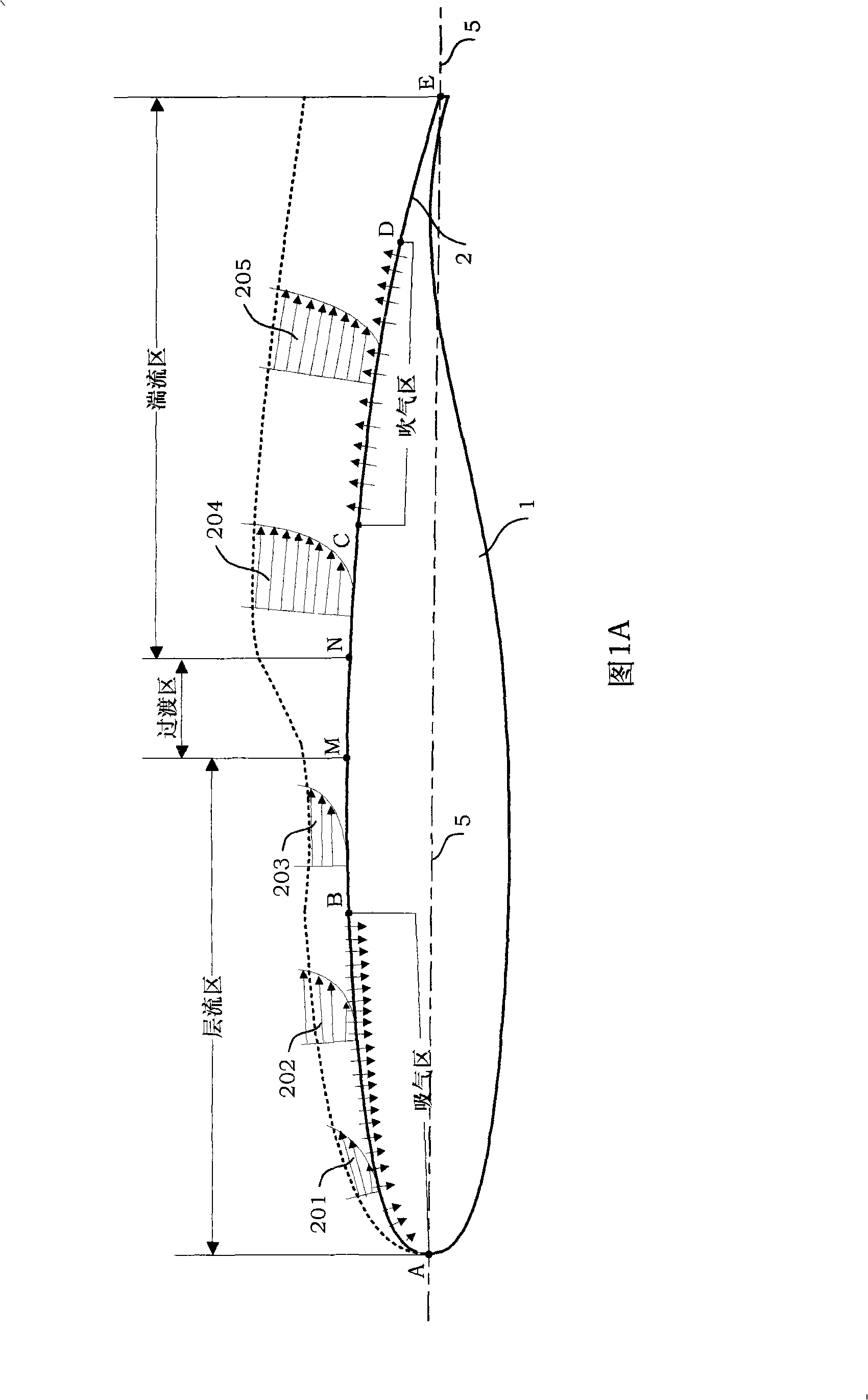
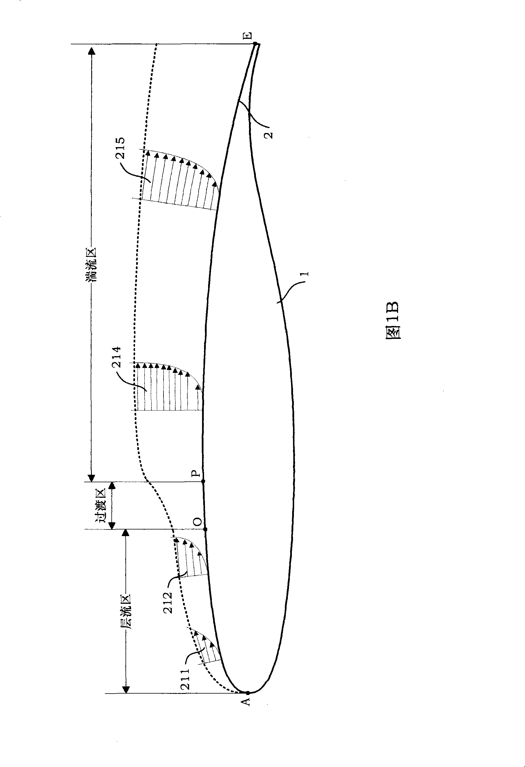
[0029] The wing structure with laminar flow control and separation control designed by the present invention is provided with a plurality of micropores with different apertures in the front and back of the upper airfoil 2 of the wing 1, and the micropores and airflow channels constitute suction, blowing passage, thereby changing the set point of the transition on the upper airfoil 2 of the wing 1. The delayed transition position can reduce frictional drag, control boundary layer separation, and improve wing stall characteristics. A plurality of suction pumps are set in the airflow channel, and by adjusting the blowing and suction volume, the low-speed fluid flowing through the bottom layer of the boundary layer on the surface of the leading edge of the airfoil can be sucked away, thereby making the boundary layer thinner and delaying the boundary layer from ...


PUM


Abstract

The invention discloses a wing structure with flow control and separation control of laminar flow. A plurality of A micropores are arranged at the front end of the vertical center line of the upper wing surface of a wing, and are neatly arranged in lines and rows to form an inspiration zone; a plurality of B micropores are arranged at the back end of the vertical center line of the upper wing surface of the wing, and are neatly arranged in lines and rows to form an air blowing zone; a communicating channel in the inspiration zone and the air blowing zone is called an air flow channel, namely, an inlet of the air flow channel is communicated with the inspiration zone, while an outlet of the air flow channel is communicated with the air blowing zone; the air flow channel is arranged in the wing; the air flow channel consists of a front air flow channel, a middle air flow channel and a back air flow channel, wherein, the middle air flow channel is in an elliptic shape; an inspiration pump is arranged in the middle air flow channel; the front air flow channel and the back air flow channel are designed into a flaring shape and are oppositely arranged. The wing of the invention can delay the transition of a bounding layer from lamina flow to turbulent flow by a control method for adjusting the capacity of blowing and inspiration so as to reduce the frictional resistance on an object surface, and can delay the flow separation so as to improve the stall performance of wing profile.

Description

technical field [0001] The present invention relates to a wing structure of a transport aircraft, more particularly, to a wing structure with laminar flow control and separation control. The wing designed by the invention can save fuel and reduce the operating cost of the transport aircraft by reducing the frictional resistance of the upper wing surface and inhibiting the separation of the boundary layer. Background technique [0002] When the airflow bypasses the wing, due to the viscosity of the airflow, there is a very thin shear layer on the airfoil (upper airfoil, lower airfoil), which is called the boundary layer. The boundary layer has two flow regimes, laminar flow and turbulent flow, and transition is the process in which the flow regime in the boundary layer transitions from laminar flow to turbulent flow (see Figure 1B). In the figure, the upper airfoil 2 of the wing is the laminar flow zone from the leading edge point A to the second transition starting point O,...

Claims


Application Information

Patent Timeline
Patent Type & Authority Applications(China)
IPC IPC(8): B64C21/02B64C23/00B64C3/36
Inventor 刘沛清段会申佟增军何雨薇陈建中
Owner BEIHANG UNIV
Why Eureka
Try Eureka