Hydraulic control mechanism for automatic clutch in hybrid electric vehicle

A hybrid electric vehicle and automatic clutch technology, applied in the field of machinery, can solve the problems of energy pulsation affecting the working performance of the switch valve, clutch hydraulic cylinder oil supply deviation, and low clutch control efficiency, so as to shorten the cost of repair and maintenance and improve Effect of control precision, improvement of control precision and response sensitivity

Pending Publication Date: 2018-01-19
NANJING YUEBOO POWER SYST CO LTD
View PDF0 Cites 0 Cited by
  • Summary
  • Abstract
  • Description
  • Claims
  • Application Information

AI Technical Summary

Problems solved by technology

[0003] At present, the clutch hydraulic control mechanism realizes the control of the oil pressure and flow direction of the hydraulic cylinder through the opening and closing of various switching valves, such as check valves, oil inlet valves, oil return valves, emergency valves, etc., so as to realize the clutch. In the separation and combination state, there is also a method of using the rotation angle of the oil pump motor to control the amount of oil supplied. This type of control method has a complex structure, and multiple valves take up too much space. When the hydraulic pump is working, the energy pulsation generated will also affect the switch. The working performance of the valve produces a deviation in the oil supply to the clutch hydraulic cylinder, which makes the control of the clutch inefficient and imprecise, resulting in a higher probability that the clutch cannot be separated and combined normally.

Method used


Image

  • Hydraulic control mechanism for automatic clutch in hybrid electric vehicle
  • Hydraulic control mechanism for automatic clutch in hybrid electric vehicle
  • Hydraulic control mechanism for automatic clutch in hybrid electric vehicle

Examples


Embodiment Construction

[0033] The technical solutions of the present invention will be described in further detail below with reference to the accompanying drawings and embodiments.

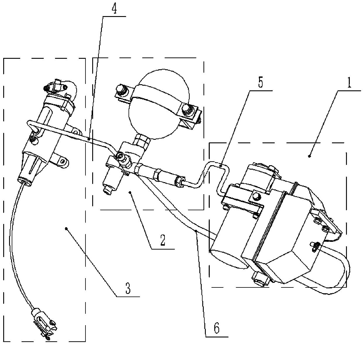
[0034] The invention provides an automatic clutch hydraulic control mechanism in a hybrid electric vehicle, such as figure 1As shown, the control mechanism includes an oil pumping system 1, an energy storage system 2, and a working cylinder system 3. A first high-pressure oil pipe 4 is connected between the energy storage system 2 and the working cylinder system 3, and the oil pumping system 1 and the energy storage system A second high-pressure oil pipe 5 and a low-pressure oil return pipe 6 are connected between the two, and a reversing valve 25 for controlling the flow direction of hydraulic oil and a pressure sensor 26 for measuring the pressure in the energy storage system 2 are installed in the energy storage system 2. An angular displacement sensor is installed in the working cylinder system 3, which is used to ...


PUM


Abstract

The invention discloses a hydraulic control mechanism for an automatic clutch in a hybrid electric vehicle. The hydraulic control mechanism comprises an oil pumping system, an energy storage system and a working cylinder system, wherein a first high-pressure oil pipe is connected between the energy storage system and the working cylinder system; a second high-pressure oil pipe and a low-pressure oil return pipe are connected between the oil pumping system and the energy storage system; a reversing valve for controlling the circulation direction of hydraulic oil and a pressure sensor used for measuring the pressure in the energy storage system are mounted in the energy storage system; a displacement sensor is mounted in the working cylinder system and used for measuring displacement of theclutch driven by the working cylinder system; and the reversing valve, the pressure sensor and the displacement sensor are all connected with a vehicle-mounted control system and can perform information exchange together with the vehicle-mounted control system. The hydraulic control mechanism is simple in structure, convenient to assemble, disassemble and maintain, and small in space occupation; and as the electronic sensing devices are adopted, the control precision and the reaction sensitivity can be improved.

Description

technical field [0001] The invention relates to the field of mechanical technology, in particular to an automatic clutch hydraulic control mechanism in a hybrid electric vehicle. Background technique [0002] In recent years, with the rapid development of new energy vehicle-related fields, hybrid power has been widely recognized by the public as a vehicle power system with good power, fast response, long working hours, low pollution and low noise. It has also become one of the mainstream automobile forms at this stage. There are also many types of clutch control mechanisms for hybrid vehicles, usually using hydraulic clutch control mechanisms. This type of clutch control mechanism has small frictional resistance, light weight, high transmission efficiency, convenient layout, soft combination, and is not affected by body deformation, etc. Features, are widely used in the middle of the clutch control mechanism. [0003] At present, the clutch hydraulic control mechanism real...

Claims


Application Information

Patent Timeline
Patent Type & Authority Applications(China)
IPC IPC(8): F16D48/06
Inventor 李占江高超蒋元广赵志专陆逊夏志勇
Owner NANJING YUEBOO POWER SYST CO LTD
Why Eureka
Try Eureka