Automatic location apparatus of benchmark template for elevator and method thereof

A reference template and automatic positioning technology, which is applied in the direction of measuring devices, transportation and packaging, elevators, etc., can solve the problem of not considering the reduction of operators, and achieve the effect of saving manpower and reducing costs

Active Publication Date: 2009-01-21
MITSUBISHI ELECTRIC BUILDING SOLUTIONS CORP
View PDF1 Cites 2 Cited by
  • Summary
  • Abstract
  • Description
  • Claims
  • Application Information

AI Technical Summary

Problems solved by technology

In the setting method of the elevator in the prior art,

Method used


Image

  • Automatic location apparatus of benchmark template for elevator and method thereof
  • Automatic location apparatus of benchmark template for elevator and method thereof
  • Automatic location apparatus of benchmark template for elevator and method thereof

Examples


Embodiment approach 1

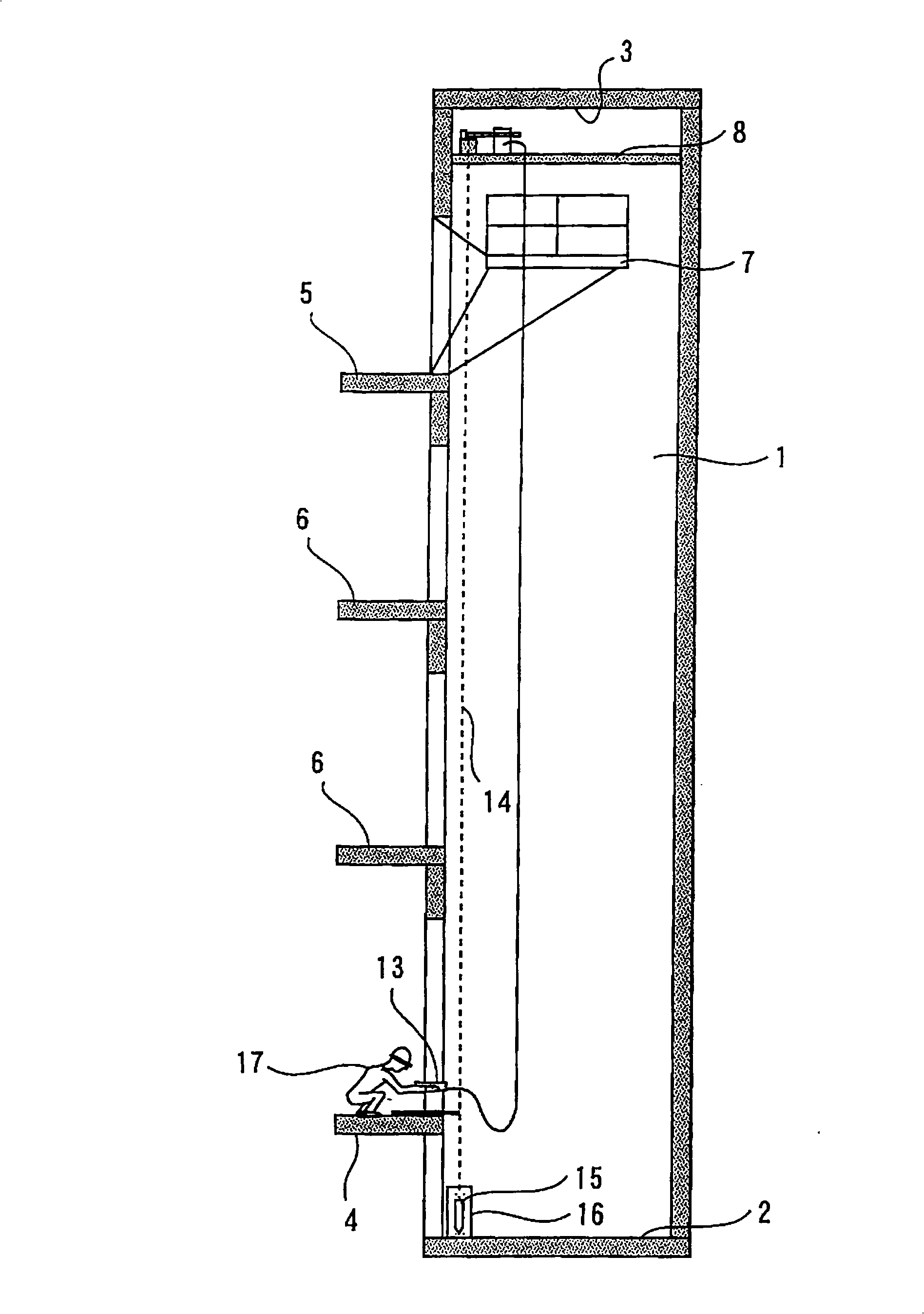
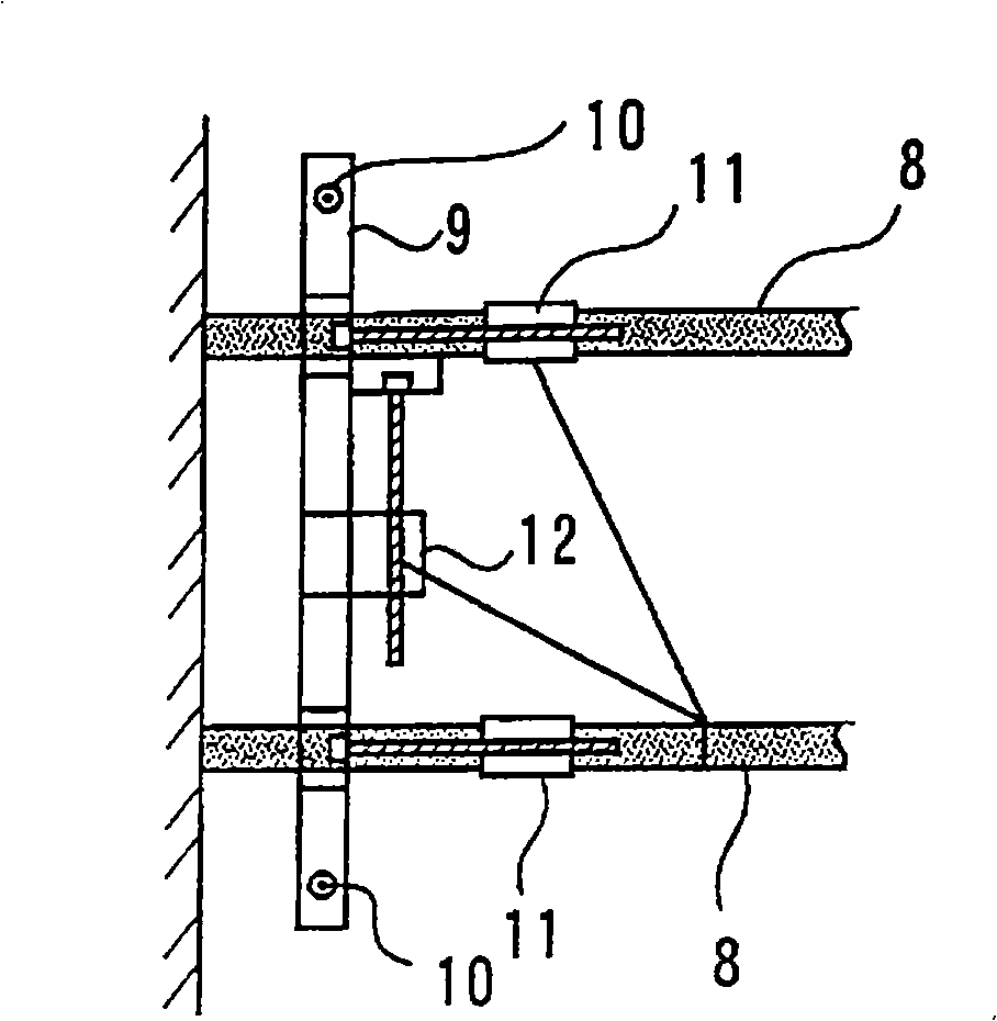
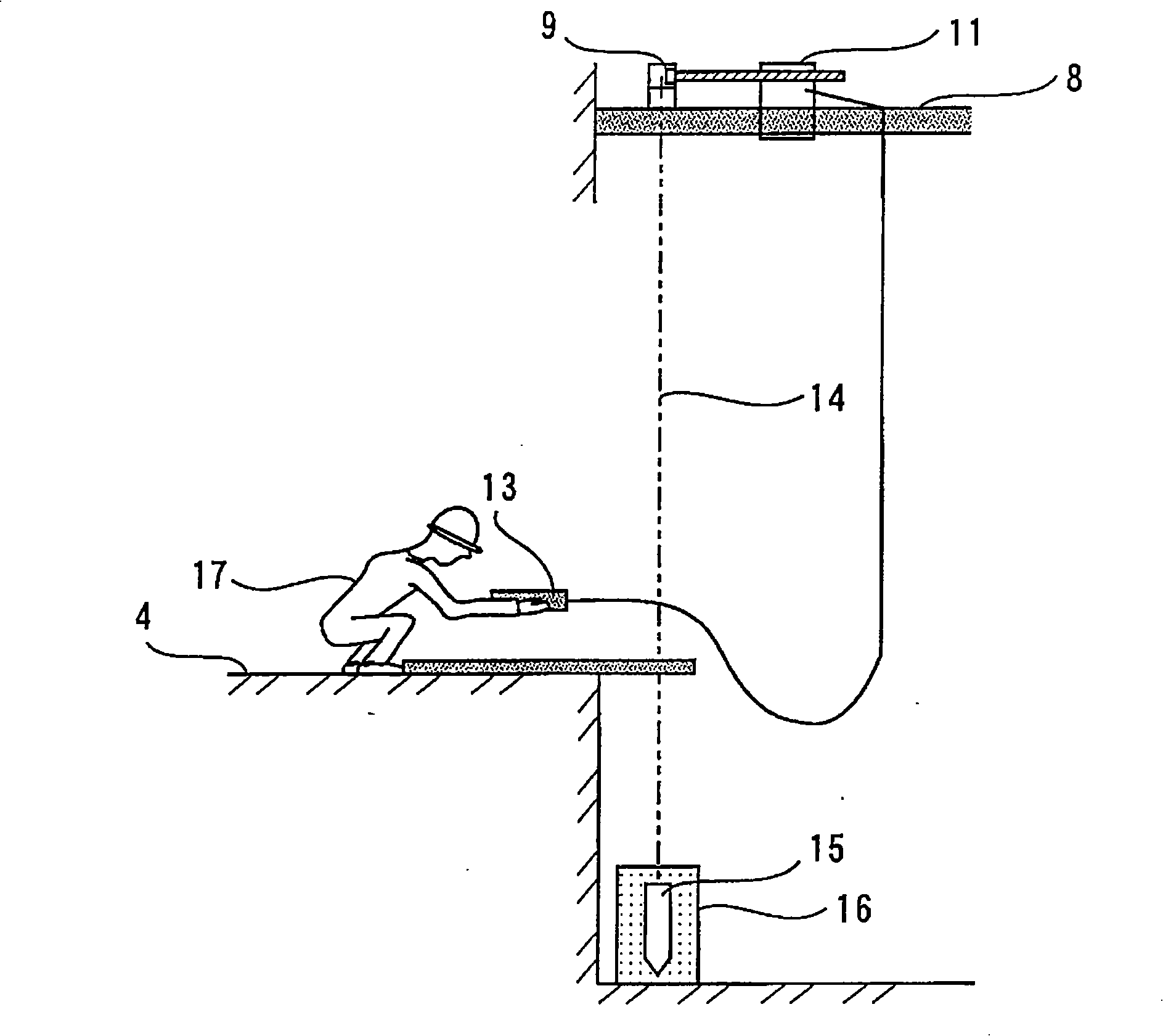
[0036] figure 1 It is an overall configuration diagram of an automatic positioning device for an elevator reference template and its method in Embodiment 1 of the present invention, figure 2 It is a partial plan view of the main part of the automatic positioning device used in the automatic positioning method of the elevator reference template in Embodiment 1 of the present invention, image 3 It is a main part side view which shows the implementation state of the automatic positioning method of the reference template for elevators in Embodiment 1 of this invention.

[0037]In the figure, 1 is the lifting path, 2 is the bottom pit of the lifting path 1, 3 is the top of the lifting path 1, 4 is the lowermost layer of the elevator room, 5 is the uppermost layer of the elevator room, and 6 is set on the lowermost layer. 4 and the middle layer formed by the multi-storey elevator room between the uppermost layer 5, 7 is the uppermost workbench arranged in the lifting path 1, and...

Embodiment approach 2

[0040] In the above-mentioned Embodiment 1, it has been explained that in the automatic positioning device and method of the reference template for elevators, the time spent on positioning the bottom piano wire becomes a problem, and most of the time spent on positioning is spent on The pendant 15 of the piano wire 14 is put into the water injection container 16 to shorten the rest time because the swing of the piano wire pendant caused by moving the template is stopped. However, in Embodiment 2, the water injection container 16 The washing agent that is made of soapy water, neutral detergent etc. replaces water, and the pendant 15 of piano wire 14 is submerged in this washing agent.

[0041] In the case of Embodiment 2, in the state where the pendant 15 is completely submerged in the detergent (100%) in the water injection container 16, the rest time is about 50 seconds, which shows the best effect of suppressing the swing of the pendant, and at the same time , Cleaning up wi...


PUM


Abstract

The invention relates to an elevator used reference template automatic positioning device which can reduce the operator in elevation direction reference positioning while installing an elevator and reduce cost. The device comprises: a template supporting mechanism (8) disposed on the top of the lifting path (1); a reference template (10) disposed cross the template supporting mechanisms equipped with a piano wire dropping unit (10) on each end; a reference template automatic positioning device (11, 12) disposed on the reference template for adjusting and controlling the planar motion in the directions of perpendicular and parallel to the lift block side; a remote control device (13) capable of operating and controlling the automatic positioning device from the bottom the lift block; piano wires (14) hung from the reference template and having a suspended weight (15) installed on lower end; and a suspended weight stilling resting watering containing (16) disposed in the lifting path pit and immersing the lower end of the suspended weight for preventing it from swinging.

Description

technical field [0001] The invention relates to an automatic positioning device and method for an elevator reference formwork, which can save the labor of the vertical reference positioning operation during elevator installation and reduce the cost. Background technique [0002] Figure 4 It shows the existing vertical reference positioning method during elevator installation. [0003] Such as Figure 4 As shown, the existing vertical reference positioning method during elevator installation is carried out according to the following steps. In the first step, the adjustment personnel 18 of the reference formwork position assemble the upper formwork assembly 19 near the top 3 of the lifting path; in the second step, the piano wire 14 is put down from the upper formwork assembly 19, and the hanging hammer 15 is hung on the piano wire 14 the lower end of. Then, in the third step, the lowermost floor benchmark confirmation personnel 20 print the lowermost floor benchmark ink li...

Claims


Application Information

Patent Timeline
IPC IPC(8): B66B7/02B66B7/00
CPCB66B7/021G01C9/12
Inventor 平川谦一郎塚本昌彦
Owner MITSUBISHI ELECTRIC BUILDING SOLUTIONS CORP
Why Eureka
Try Eureka