Full section ladder energy dissipater

An energy-dissipating, full-section technology, applied in water conservancy projects, marine engineering, coastline protection, etc., can solve problems such as increased energy dissipation rate, inability to guarantee energy dissipation rate, etc. the effect of destruction

Inactive Publication Date: 2009-01-21
SICHUAN UNIV
View PDF4 Cites 31 Cited by
  • Summary
  • Abstract
  • Description
  • Claims
  • Application Information

AI Technical Summary

Problems solved by technology

Studies have shown that if energy dissipators are installed on the spillway floor, the energy dissipation rate increases with the increase of the step height, and decreases with the increase of the single-width flow of t

Method used


Image

  • Full section ladder energy dissipater
  • Full section ladder energy dissipater
  • Full section ladder energy dissipater

Examples


Embodiment 1

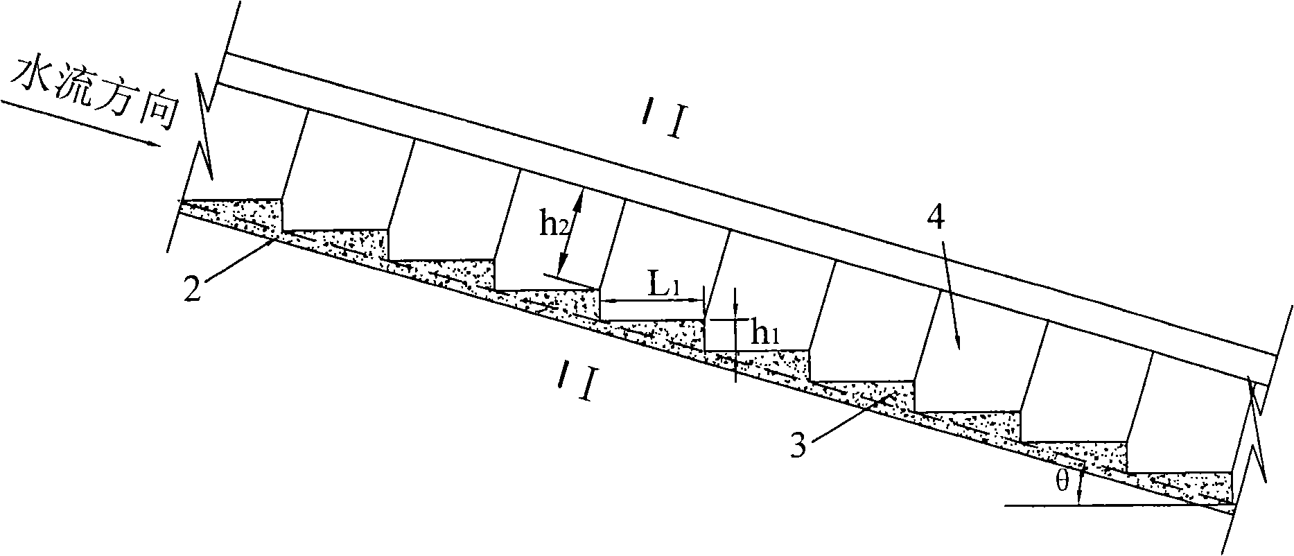
[0047] The full-section ladder energy dissipator in this embodiment is used in the project hub of the power station, the maximum working water head of the spillway of the power station is 140m, and the maximum discharge flow Q=1000m 3 / s, maximum single width flow q=100m 3 / s.m, spillway width B=10m, side wall height H=8m, floor slope θ is 15°.

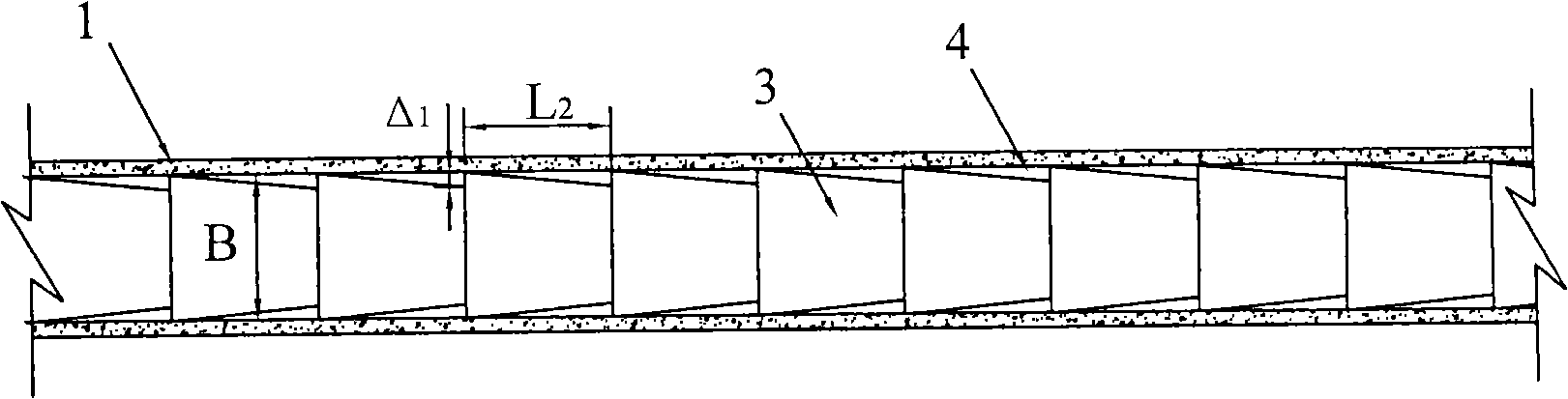
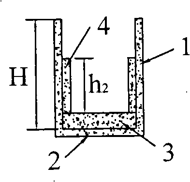
[0048] The full-section ladder energy dissipator in this embodiment has a structure such as figure 1 , figure 2 , image 3As shown, it consists of stepped energy dissipators arranged on the spillway floor 2 and stepped energy dissipators arranged on the walls 1 on both sides of the spillway. The step of the ladder energy dissipator arranged on the spillway floor 2 is a horizontal step, the cross section of the step is triangular, and the step length is L 1 =7.5m, step height h 1 = 2m. The ladder shape of the ladder energy dissipator arranged on the walls 1 on both sides of the spillway is as follows: Figure 4 As shown, it is ...

Embodiment 2

[0051] The full-section ladder energy dissipator in this embodiment is used in a flood discharge tunnel of a hydropower station. The maximum working water head of the flood discharge tunnel is 150m, and the maximum discharge flow Q=1500m 3 / s, maximum single width flow q=150m 3 / s.m, spillway width B=10m, side wall height H=10m, floor slope θ is 25°.

[0052] The full-section ladder energy dissipator in this embodiment has a structure such as Figure 5 , Figure 6 , Figure 7 As shown, it consists of stepped energy dissipators arranged on the floor 2 of the spillway tunnel and stepped energy dissipators arranged on the walls 1 on both sides of the spillway tunnel. The step of the ladder energy dissipator arranged on the bottom plate 2 of the spillway tunnel is a horizontal ladder, the section of the ladder is triangular, and the length of the ladder is L 1 =4.3m, step height h 1 = 2.0m. The ladder shape of the ladder energy dissipator arranged on the walls 1 on both side...

Embodiment 3

[0055] The full-section ladder energy dissipator in this embodiment is used in the project hub of the power station, the maximum working water head of the spillway of the power station is 140m, and the maximum discharge flow Q=1000m 3 / s, maximum single width flow q=100m 3 / s.m, spillway width B=10m, side wall height H=8m, floor slope θ is 15°.

[0056] The full-section ladder energy dissipator in this embodiment has a structure such as Figure 8 , Figure 9 , Figure 10 As shown, it consists of stepped energy dissipators arranged on the spillway floor 2 and stepped energy dissipators arranged on the walls 1 on both sides of the spillway. The step of the ladder energy dissipator arranged on the spillway floor 2 is a horizontal step, the cross section of the step is triangular, and the step length is L 1 =7.5m, step height h 1 = 2m. The ladder shape of the ladder energy dissipator arranged on the walls 1 on both sides of the spillway is as follows: Figure 11 As shown, i...


PUM


Abstract

The invention discloses a full-section stepped energy dissipater, which consists of stepped energy dissipaters arranged on a bottom slab of a spillway or a floor discharge tunnel and stepped energy dissipater arranged on two side walls of the spillway or the floor discharge tunnel, namely the bottom slab and the two side walls of the spillway or the floor discharge tunnel are provided with the stepped energy dissipaters. The full-section stepped energy dissipater has the following energy dissipation mechanism that: when waterflow passes through steps on the bottom slab, the falling, the whirling and the shearing action of the waterflow appear, and the air above the water surface is involved into a water body; steps on the side walls sharpen the turbulent motion of the waterflow, which improves energy dissipation effect and ensures that the waterflow constantly contracts and expands along the way to form cavities at both sides so that the airflow enters the surfaces of the steps of the bottom from the cavities to cause the waterflow of the whole section to be fully aerated, thereby avoiding adverse effects such as cavitation erosion and so on.

Description

technical field [0001] The invention relates to a stepped energy dissipator for a large single wide flow spillway or a spillway. Background technique [0002] Spillways (spill tunnels) generally have the characteristics of large drop and large discharge volume. For projects with spacious downstream rivers and good geological conditions, deflected flow energy dissipation is often used. For mountainous rivers, due to the narrow river channel, deflected flow energy dissipation is used. The outlet flow rate is very high. Large, unfavorable to the downstream. With the development of RCC technology, ladder construction is more convenient, and the ladder is easy to repair and restore. Therefore, the application of ladder energy dissipators in spillways has been promoted, but the ladder energy dissipators used in existing spillways are all set on the floor of the spillway. Studies have shown that if energy dissipators are installed on the spillway floor, the energy dissipation rat...

Claims


Application Information

Patent Timeline
IPC IPC(8): E02B8/06
Inventor 张建民许唯临王韦刘善均曲景学邓军田忠张法星李贵吉王曾恩陈剑刚
Owner SICHUAN UNIV
Why Eureka
Try Eureka