Fan with sensing element bearing structure and fan frame thereof

A technology for sensing elements and bearing structures, applied to pump elements, parts of pumping devices for elastic fluids, non-variable pumps, etc., can solve problems such as damage to sensing elements

Inactive Publication Date: 2009-01-21
DELTA ELECTRONICS INC
View PDF0 Cites 4 Cited by
  • Summary
  • Abstract
  • Description
  • Claims
  • Application Information

AI Technical Summary

Problems solved by technology

[0006] Because of this, how to avoid damage to the sensing elem

Method used


Image

  • Fan with sensing element bearing structure and fan frame thereof
  • Fan with sensing element bearing structure and fan frame thereof
  • Fan with sensing element bearing structure and fan frame thereof

Examples


Embodiment Construction

[0028] A sensing element carrying structure and a fan thereof according to preferred embodiments of the present invention will be described below with reference to related drawings.

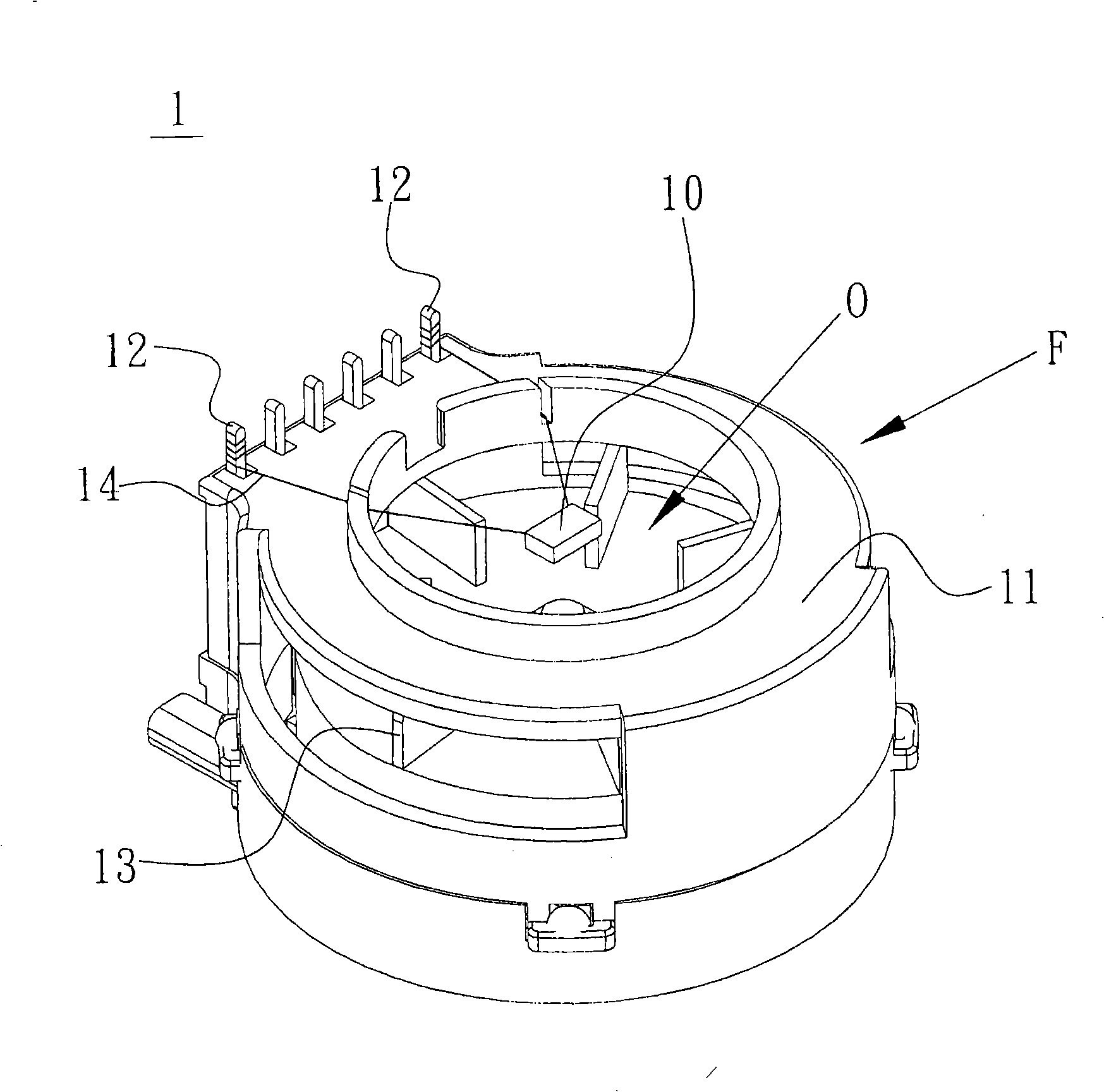
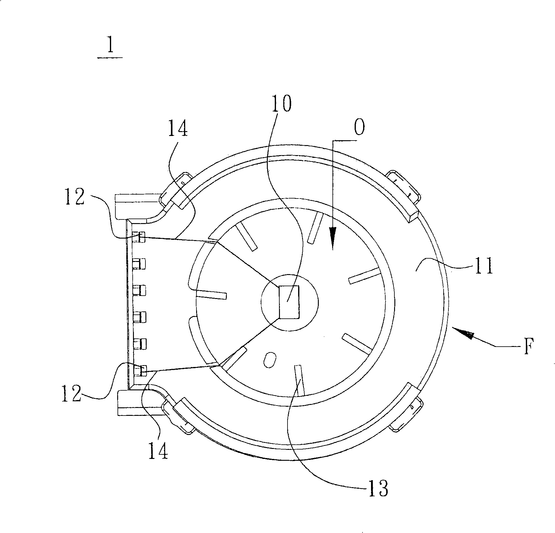
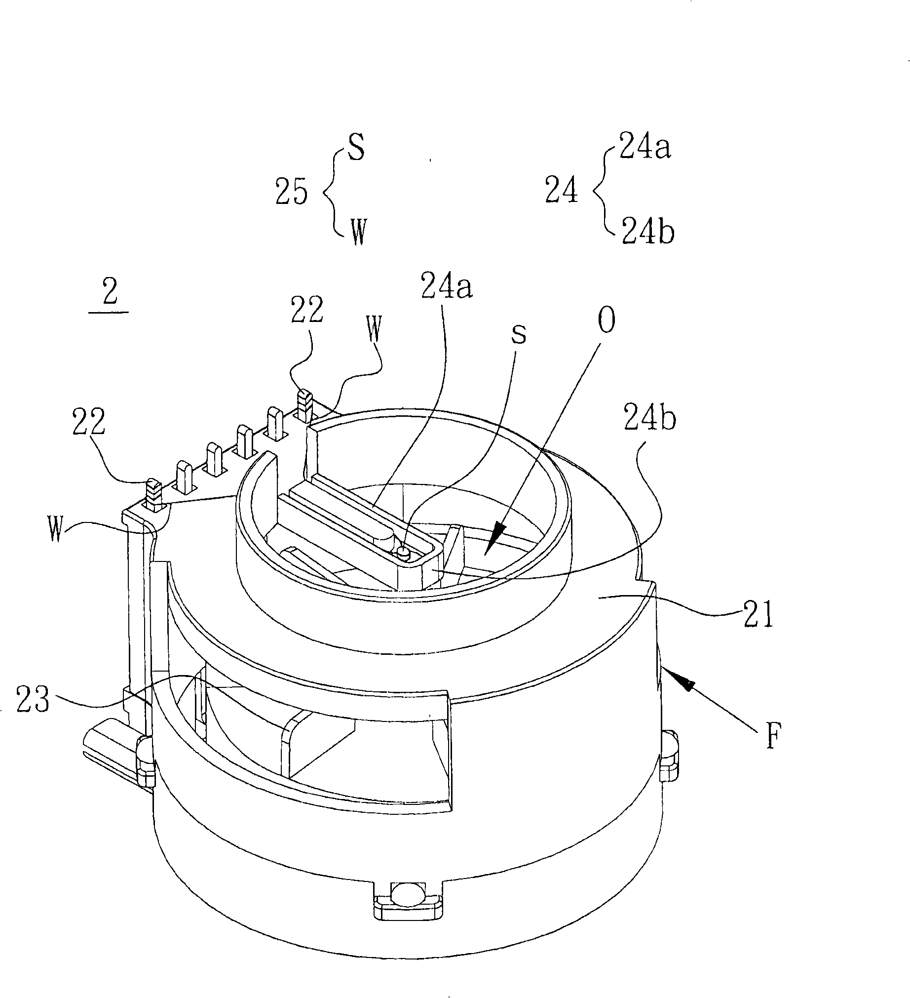
[0029] Please also refer to Figure 2A to Figure 2C , a fan 2 with a sensing element bearing structure according to the present invention, which includes a fan frame F, and the fan frame F forms an air inlet O for air to pass through and enter the inside of the fan 2 . The fan frame F includes a body 21 and a sensing element carrying structure 24. The sensing element carrying structure 24 protrudes from the body 21 to the air inlet O air passage area to carry or accommodate a sensor with a wire part W and elements. The sensing element 25 of the part S.

[0030] The fan 2 further includes a stator 27 and a rotor 26 arranged in the fan frame F, the rotor 26 is rotated by electromagnetic induction to drive a fan blade 23 connected to the rotor 26 to generate air flow, and the other connecting porti...


PUM


Abstract

The invention discloses a fan with a sensing element bearing structure and a fan frame of the fan, which comprises a fan frame, a stator and a rotor with fan leaves. The fan frame comprises a body and a sensing element bearing structure, and the sensing element bearing structure extends to a wind inlet from the body. The stator and the rotor are arranged inside the fan frame, and the sensing element bearing structure is used to bear sensing elements.

Description

technical field [0001] The invention relates to a fan with a sensing element bearing structure and its fan frame, in particular to a sensing element bearing structure on the fan, which can improve the reliability of product use. Background technique [0002] With the high development of technology and the improvement of consumers' taste, the requirements for the functions of automotive electronic equipment are also higher, especially for the air-conditioning system in the car. It has become a necessary condition for the current car design to provide a suitable temperature space for the driver and passengers. [0003] The early vehicle constant temperature control design mainly transmits the temperature to the sensor embedded in the vehicle body through a temperature sensing conductor protruding from the vehicle body, and then feeds back the measured temperature value to the vehicle computer through the circuit system. Adjust the air conditioning system. [0004] However, th...

Claims


Application Information

Patent Timeline
IPC IPC(8): F04D29/42F04D29/62
Inventor 陈孟钰庄德财
Owner DELTA ELECTRONICS INC
Why Eureka
Try Eureka