Bipolar plate with microgrooves for improved water transport

A bipolar plate and micro-groove technology, applied in battery electrodes, fuel cell components, electrolyte treatment of solid electrolyte batteries, etc., can solve problems such as limiting long-term durability and increasing battery ionic resistance

Inactive Publication Date: 2009-01-21
GM GLOBAL TECH OPERATIONS LLC
View PDF5 Cites 24 Cited by
  • Summary
  • Abstract
  • Description
  • Claims
  • Application Information

AI Technical Summary

Problems solved by technology

Dry inlet gas has a drying effect on the membrane, which can increase the ionic resistance of the cell and limit the long-term durability of the membrane

Method used


Image

  • Bipolar plate with microgrooves for improved water transport
  • Bipolar plate with microgrooves for improved water transport
  • Bipolar plate with microgrooves for improved water transport

Examples


Embodiment Construction

[0033] The following descriptions of embodiments are merely illustrative in nature and do not limit the invention, its application or use.

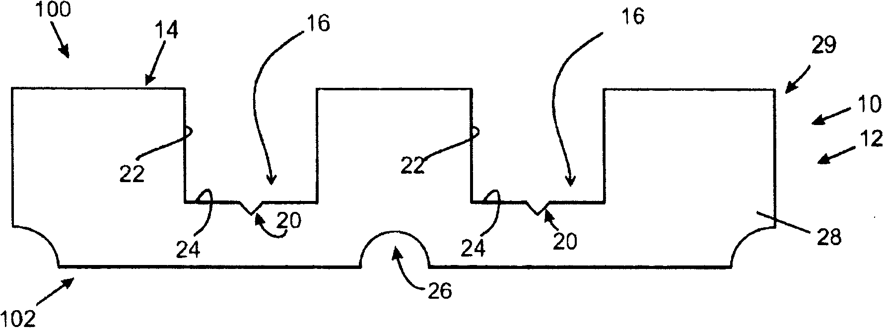
[0034] now refer to figure 1 , an embodiment of the invention includes a product 10 having a fuel cell bipolar plate 12 . The fuel cell bipolar plate 12 includes a substrate 29 . Substrate 29 includes base portion 28 and optionally one or more layers on base portion 28 . Base portion 28 includes a variety of materials including, but not limited to, metals, metal alloys, and / or conductive composite materials. Base portion 28 may include one or more layers.

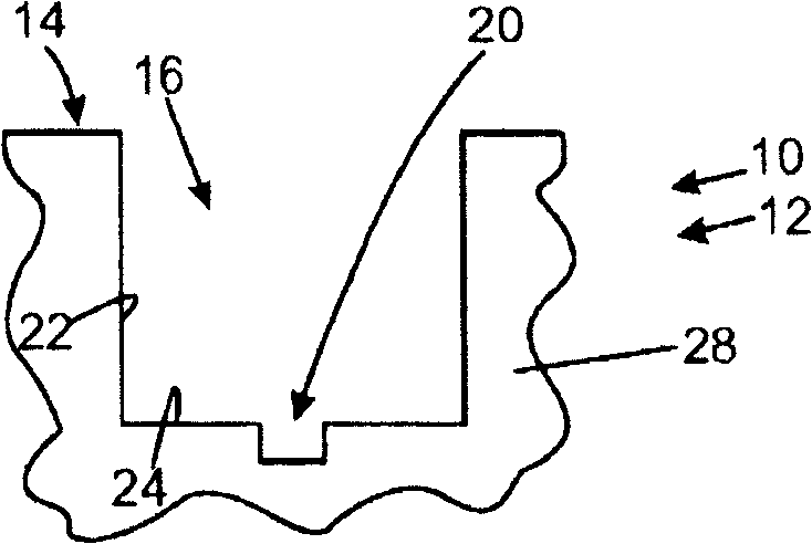
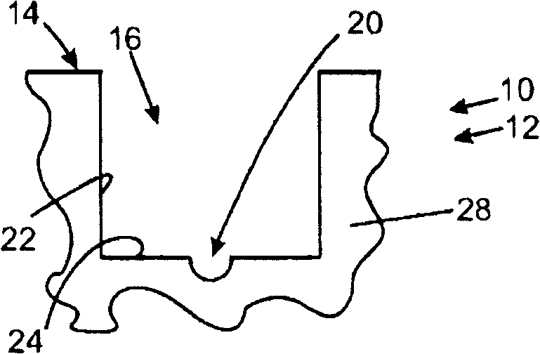
[0035] The fuel cell bipolar plate 12 includes a first face 100 and an opposing second face 102 . The fuel cell bipolar plate 12 includes a reactant gas flow field defined at least in part by a plurality of platforms 14 and channels 16 in a first face 100 . Channel 16 is defined by side walls 22 and a bottom surface 24 . Cooling channels 26 may be formed in second face 102 .

[...


PUM


Abstract

The present invention relates to a bipolar plate with microgrooves for improving water transport. One embodiment of the invention comprises a fuel cell bipolar plate comprising a substrate comprising a first face, a reactant gas flow field defined in the first face, the reactant gas flow field comprising a plurality of lands and channels, and a plurality of microgrooves formed in the first face.

Description

technical field [0001] The field to which this disclosure relates generally includes bipolar plates for fuel cells, and more particularly to bipolar plates having microgrooves formed therein. Background technique [0002] Hydrogen is a very attractive fuel because it is clean and can be used to efficiently generate electricity in fuel cells. The automotive industry has expended significant resources in developing hydrogen fuel cells as a vehicle power source. Such vehicles are more efficient and produce fewer emissions than today's vehicles with internal combustion engines. [0003] A hydrogen fuel cell is an electrochemical device that includes an anode and a cathode with an electrolyte positioned between the anode and cathode. The anode receives hydrogen-rich gas or pure hydrogen and the cathode receives oxygen or air. Hydrogen gas is decomposed in the anode to produce free protons and electrons. The protons travel through the electrolyte to the cathode, where they rea...

Claims


Application Information

Patent Timeline
Patent Type & Authority Applications(China)
IPC IPC(8): H01M8/02H01M4/86
CPCY02E60/50H01M8/04291H01M8/0245H01M2008/1095H01M8/04171H01M8/026Y10T29/49108
Inventor T·A·特拉博德G·V·达希奇M·H·阿布德埃尔哈米德Y·张K·E·纽曼J·A·罗克S·J·斯潘塞
Owner GM GLOBAL TECH OPERATIONS LLC
Why Eureka
Try Eureka