Armrest drive force monitoring apparatus of passenger conveying equipment

A technology of passenger conveying equipment and monitoring devices, which is applied in escalators, transportation and packaging, etc., can solve the problems of undetectable driving force, increased equipment structure cost, and increased program processing burden, and achieves excellent detection accuracy and the shortest time Optimizing and improving the effect of reliability

Active Publication Date: 2009-01-28
HITACHI BUILDING SYST CO LTD +1
View PDF2 Cites 16 Cited by
  • Summary
  • Abstract
  • Description
  • Claims
  • Application Information

AI Technical Summary

Problems solved by technology

[0008] However, in the known technology described in the above-mentioned Patent Document 1, since it counts the speed detection data reaching the preset speed range, when the friction coefficient between the driving roller and the handrail has actually decreased and the handrail is actually broken, The average speed has also been reduced, but since the speed amplitude is large, if the number of speed detection data that reaches the set speed range does not decrease, it cannot detect driving force abnormalities, so the diagnostic accuracy may decrease
[0009] In addition, in the known technology described in Patent Document 2 that corrects the belt slippage rate, since it is necessary to install rotation detectors on both sides of the belt transmission system, and it is necessary to monitor the slippage rate based on the rotation difference all the time, the program processing Increases the burden and tends to increase the cost of the equipment structure

Method used


Image

  • Armrest drive force monitoring apparatus of passenger conveying equipment
  • Armrest drive force monitoring apparatus of passenger conveying equipment
  • Armrest drive force monitoring apparatus of passenger conveying equipment

Examples


no. 1 approach

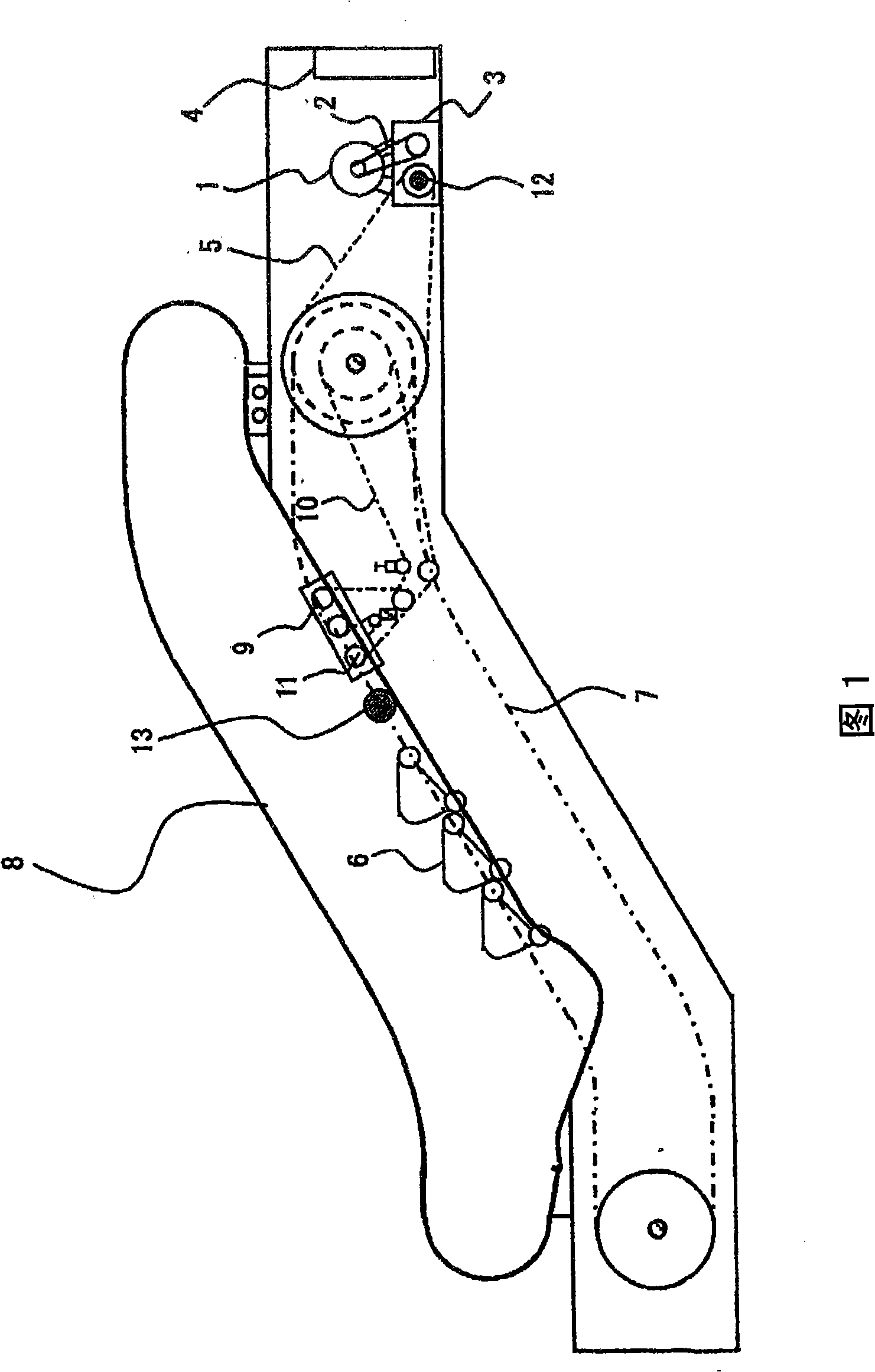
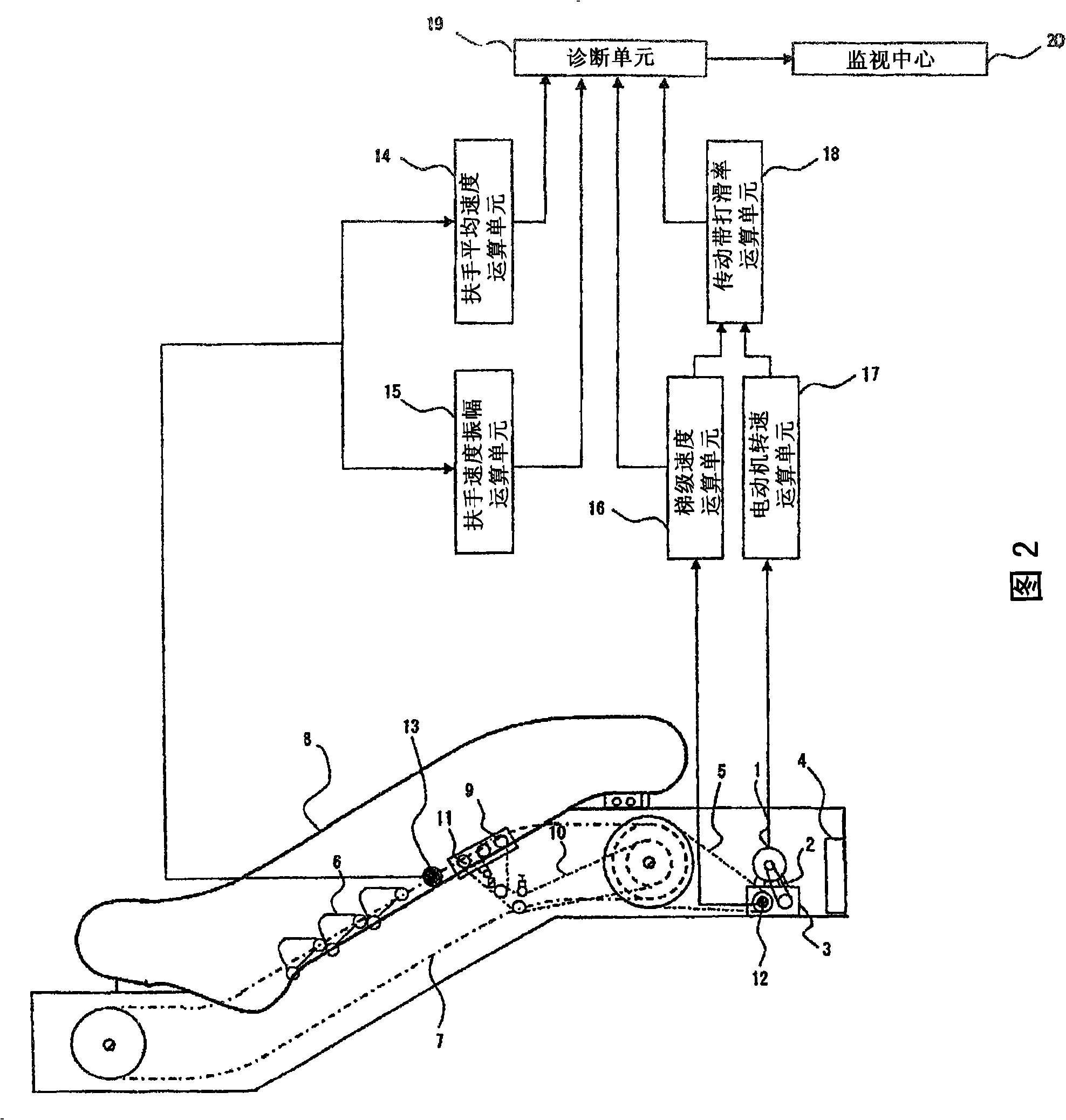
[0053] Fig. 2 is a functional block diagram showing, for example, a first embodiment of the handrail driving force monitoring device according to the present invention in the escalator shown in Fig. 1 .

[0054]As shown in Figure 2, in the first embodiment, there is a handrail average speed calculation unit 14 and a handrail speed amplitude calculation unit 15, wherein the handrail average speed calculation unit 14 is used to read the output signal of the handrail speed detector 13, to Count the total number of pulses output by the end of the predetermined distance walking, and divide the total number of pulses by the time required for walking to calculate the average speed V1 of the handrail 8 rotating one circle. The handrail speed amplitude calculation unit 15 uses V1 and read the same data, and generate the speed data of the handrail 8 according to the preset pulse number of each sample, and extract the minimum and maximum values ​​of the generated speed data to calculate t...

no. 2 approach

[0068] Figure 7 It is a functional block diagram showing the second embodiment of the present invention. exist Figure 7 In the second embodiment shown, the following devices are added to the structure of the above-mentioned first embodiment.

[0069] In the second embodiment, considering that when there are many passengers, the average speed V1 of the handrail 8 may sometimes fluctuate due to reasons such as passengers holding the handrail, in order to approximate the diagnostic conditions, a calculation of the passenger load factor is provided. The unit 21 calculates the passenger load rate based on the information of the drive torque control device 4, so as to limit the reading of the output signals of the step speed detector 12 and the handrail speed detector 13 to the time when there are no passengers or few passengers.

[0070] In addition, it also has a reading judging unit 22 and an output signal storage unit 23, wherein the reading judging unit 22 stores and update...


PUM


Abstract

The invention provides a handrail driving force monitoring device of passenger conveying device capable of reducing the cost of the monitoring system and ensuring the excellent diagnostic accuracy; wherein, the device is equipped with a handrail mean velocity calculating unit (14) which calculates the mean velocity V1 of the handrail (8) by utilizing the output signal 1 of the handrail speed detector (13); a handrail speed amplitude calculating unit (15) which calculates the speed amplitude value delta V of the handrail by utilizing the output signal 1; a motor rotational speed calculating unit (17) which judges the rotational speed driving the motor (1) according to the information driving the torque control device (4); a passenger load ratio calculating unit (21) which calculates the passenger load ratio according to the information driving the torque control device; and a diagnostic unit (19) which diagnosticates whether the handrail driving force is normal according to the mean velocity V1 and the speed amplitude value delta V; wherein, the mean velocity V1 is calculated by utilizing the output signal 1 output lower than the preset passenger load ratio and the output signal 2 of the step speed detector (12).

Description

technical field [0001] The present invention relates to a handrail driving force monitoring device for passenger conveying equipment, which automatically monitors the handrail driving force of the handrail driving device, so that the adjustment work instruction can be reliably planned before the driving force exceeds the management value, and the Armrest drive function is always maintained in proper condition. Background technique [0002] As a known handrail driving force monitoring device of passenger conveying equipment, there is a device described in Patent Document 1, for example. In this known technology, a handrail speed detector is provided to count the speed data reaching a preset handrail speed range, so that the abnormality of the driving force can be judged according to the change of the counted value. [0003] According to the record of this known technology, because it adopts the structure that can judge the downward trend of the driving force of the handrail ...

Claims


Application Information

Patent Timeline
Patent Type & Authority Applications(China)
IPC IPC(8): B66B29/00B66B25/00B66B23/04B66B23/02
Inventor 坂上充一濑卓也五十岚芳治盐山纯八卷正光
Owner HITACHI BUILDING SYST CO LTD
Why Eureka
Try Eureka